
Ray apparatus shell and ray apparatus

A technology of optics and housings, applied in optics, optical components, installation, etc., can solve the time-consuming and labor-intensive problems of manual assembly

Pending Publication Date: 2018-07-24
ZHEJIANG CRYSTAL OPTECH
View PDF10 Cites 2 Cited by
  • Summary
  • Abstract
  • Description
  • Claims
  • Application Information

AI Technical Summary

Problems solved by technology

[0004] The purpose of the present invention is to provide a material return device and ignition coil terminal assembly equipment to alleviate the time-consuming and labor-intensive technical problems of manual assembly in the existing terminal production process

Method used


Image

  • Ray apparatus shell and ray apparatus
  • Ray apparatus shell and ray apparatus
  • Ray apparatus shell and ray apparatus

Examples


Embodiment Construction

[0028] The technical solutions of the present invention will be clearly and completely described below in conjunction with the accompanying drawings. Obviously, the described embodiments are part of the embodiments of the present invention, rather than all of them. Based on the embodiments of the present invention, all other embodiments obtained by those of ordinary skill in the art without creative work shall fall within the protection scope of the present invention.

[0029] In the description of the present invention, it should be noted that if the terms "center", "upper", "lower", "left", "right", "vertical", "horizontal", "inner", "outer" appear ", etc., the indicated position or positional relationship is based on the position or positional relationship shown in the drawings, which is only for the convenience of describing the present invention and simplifying the description, and does not indicate or imply that the pointed device or element must have a specific position, I...


PUM


Abstract

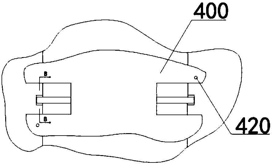
The invention provides a ray apparatus shell and a ray apparatus and relates to the technical field of ray apparatus preparation. The ray apparatus shell comprises a trough body and a positioning pressure plate, wherein slots are correspondingly formed in two opposite inner side walls of the trough body along a depth direction of the trough body; the slots are used for inserting lenses; the positioning pressure plate comprises a boss part; a positioning groove is formed in the boss part, so that the positioning pressure plate is fixed on two upper end faces of the trough body; and the groove bottom of the positioning groove pops up an upper edge of the lens, and the lens is perpendicular to the bottom surface of the groove body. An original manner of positioning the slots in the left and right side walls is modified as a manner of top and bottom positioning fixed by utilizing the bottom of the trough body and the bottom surface of the positioning groove, the tilting degree of the lensrelative to the depth of the trough body is reduced, and the tilting degree of the lens in a vertical direction is in a preset range.

Description

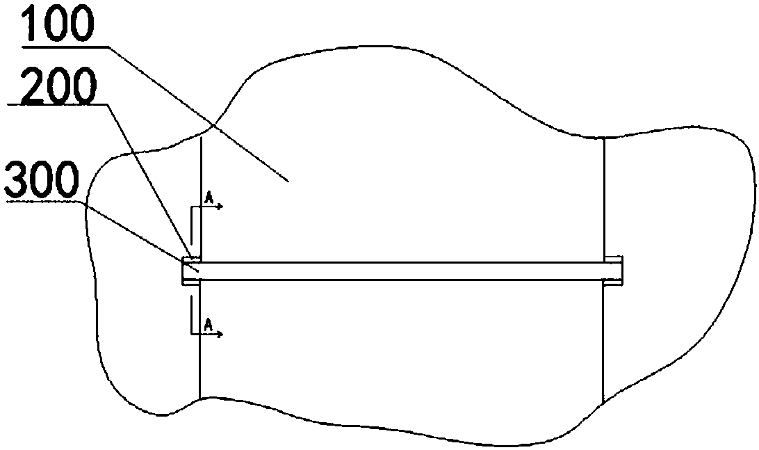
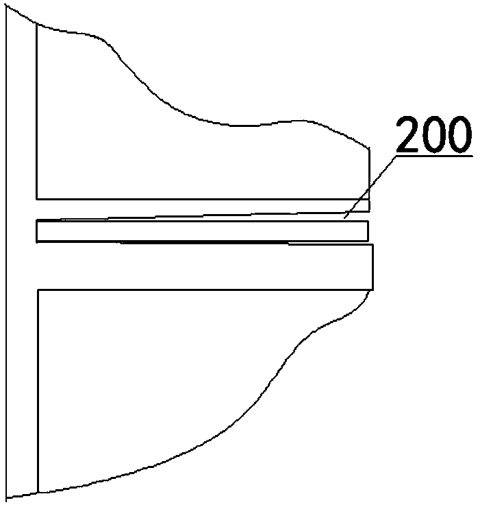
Technical field [0001] The present invention relates to the technical field of optical machine preparation, in particular to an optical machine housing and an optical machine. Background technique [0002] A groove body is arranged in the optical engine housing, and two slots for inserting the lens are arranged on two opposite sides of the groove body, and the lens is fixed in the groove body by the side positioning method. However, because the opto-mechanical housing is integrally formed by casting and pressing, when the slot is formed, it is bound to form a certain draft angle. For optical products, the angle of some lenses has an impact on product performance. Very big. [0003] figure 1 It is a top view of the lens fixed in the existing optical engine housing, figure 2 for figure 1 A cross-sectional view in the direction of A-A. It can be seen from the figure that from bottom to top, the two inner side walls of the slot have a certain slope, so the lens fixed in the slot will...

Claims


Application Information

Patent Timeline
IPC IPC(8): G02B7/02
CPCG02B7/02
Inventor 陈凯
Owner ZHEJIANG CRYSTAL OPTECH
Learn More