Integrated electrode structure applicable to mechanical type direct current circuit breaker, and driving method of integrated electrode structure

A DC circuit breaker and electrode structure technology, which is applied to circuit breaker components, circuit breaker contacts, circuits, etc., can solve the problems of high cost, large volume, and poor coordination, and achieve the effect of rapid closing and opening

Active Publication Date: 2018-07-24
XI AN JIAOTONG UNIV
View PDF7 Cites 0 Cited by
  • Summary
  • Abstract
  • Description
  • Claims
  • Application Information

AI Technical Summary

Problems solved by technology

Among them, the air ball gap switch has certain safety hazards due to the air arc generated when it is turned on, so it is not suitable for many occasions; the vacuum arc in the vacuum ball gap switch is easy to extinguish when the oscillating current crosses zero, resulting in LC oscillation The circuit stops working, so the current freewheeling performance of the switch is relatively poor; the controllable power semiconductor device is only suitable for low voltage and low current occasions due to its low withstand voltage and small conduction current.
Traditional mechanical switches have disadvantages such as large dispersion, slow opening and closing speed, and insufficient mechanical strength, which limit the performance of the entire DC circuit breaker
At the same time, the above three switches all have the disadvantages of many auxiliary components, high cost, large volume, poor compatibility, and low reliability.

Method used


Image

  • Integrated electrode structure applicable to mechanical type direct current circuit breaker, and driving method of integrated electrode structure
  • Integrated electrode structure applicable to mechanical type direct current circuit breaker, and driving method of integrated electrode structure

Examples


Embodiment Construction

[0021] The technical solutions of the present invention will be further described below in conjunction with the accompanying drawings and specific embodiments.

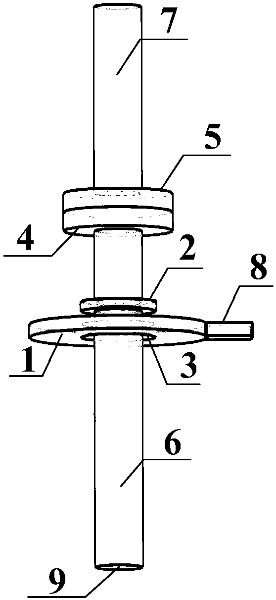
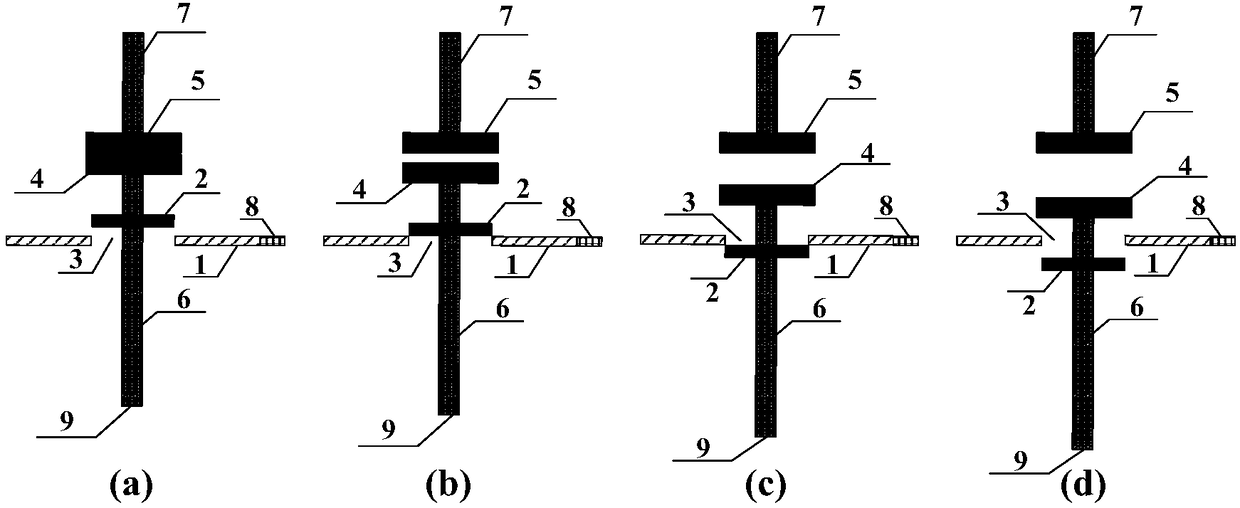
[0022] The invention provides an integrated electrode structure suitable for mechanical DC circuit breakers, such as figure 1 As shown, the integrated electrode structure includes a movable conductive rod 6, one end of the movable conductive rod 6 is provided with an active electrode 4, the main static electrode 5 is arranged opposite to the active electrode 4, and the movable conductive rod 6 is also provided with an auxiliary movable electrode 2, There is a certain gap between the auxiliary moving electrode 2 and the active electrode 4, and the auxiliary moving electrode 2 is correspondingly provided with an auxiliary static electrode 1; wherein, when the moving conductive rod 6 drives the active electrode 4 and the auxiliary moving electrode 2 to move, when the active electrode 4 and the main static electrode 5 are...


PUM


Abstract

The invention discloses an integrated electrode structure applicable to mechanical type direct current circuit breaker, and a driving method of the integrated electrode structure. The integrated electrode structure comprises a moving conductive rod; a main moving electrode is arranged at one end of the moving conductive rod; an auxiliary moving electrode is arranged on the moving conductive rod; the main moving electrode is correspondingly provided with a main static electrode; the main static electrode is connected to one end of a static conductive rod; the auxiliary moving electrode is correspondingly provided with au auxiliary static electrode; the auxiliary static electrode is connected with an auxiliary static electrode lead end, wherein the moving conductive rod drives the main moving electrode and the auxiliary moving electrode to perform linear motion. By virtue of the electrode structure, the main electrode and the auxiliary moving electrode can be driven synchronously by onemoving conductive rod, so that quick on and off of the auxiliary electrode can be realized when the main electrode is switched on or off; and the auxiliary electrode can be adjusted to be kept in theswitch-on state by changing the dimension of the auxiliary electrode or the movement speed of the moving conductive rod.

Description

technical field [0001] The invention belongs to the technical field of power switches; in particular, it relates to an integrated electrode structure suitable for a mechanical DC circuit breaker; and also relates to a driving method for the integrated electrode structure. Background technique [0002] With the development of DC grid technology, the production, transmission, distribution and consumption of electric energy are gradually moving towards the direction of high efficiency and environmental protection. Compared with the traditional AC grid, the DC grid mainly has the advantages of large transmission power, low loss, and high stability. However, since the direct current does not have a natural zero-crossing point, the current technology for breaking the direct current is immature, which has become a major bottleneck for the further development of the direct current grid. [0003] At present, there are mainly three types of design schemes for DC circuit breakers: mec...

Claims


Application Information

Patent Timeline
Patent Type & Authority Applications(China)
IPC IPC(8): H01H71/08H01H73/04H01H9/00
CPCH01H9/0066H01H71/08H01H73/04H01H2071/086
Inventor 史宗谦李昇贾申利
Owner XI AN JIAOTONG UNIV
Why Eureka
Try Eureka