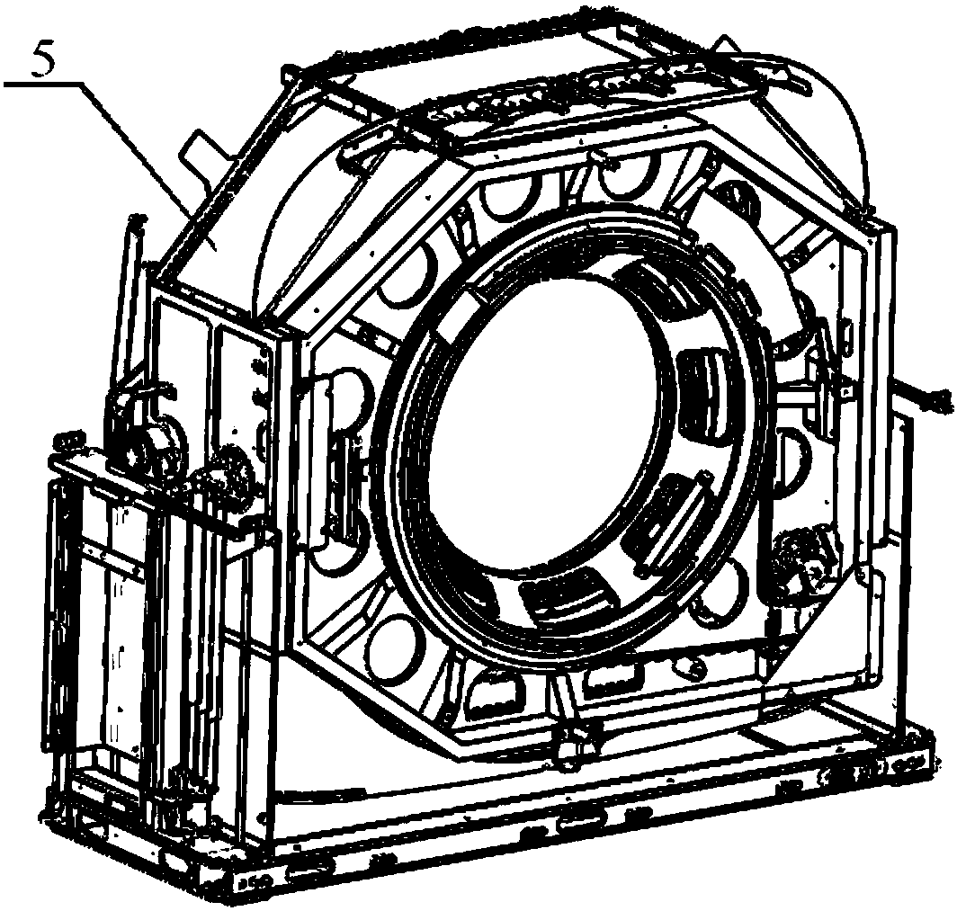
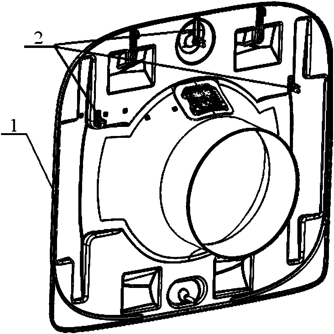
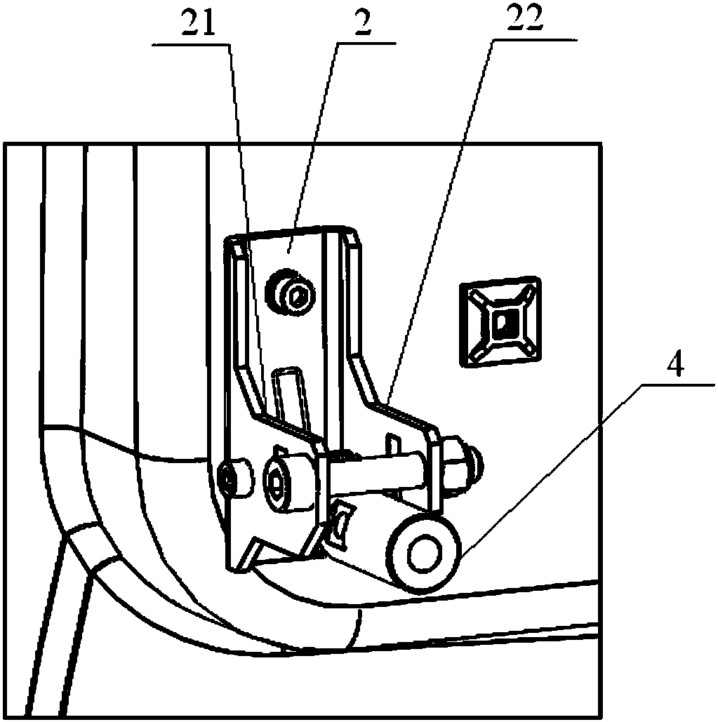
CT (computer chromatography) machine and locking device for rear cover of CT machine
A technology of locking device and back cover, which is applied in the fields of radiological diagnostic instruments, medical science, diagnosis, etc., can solve problems such as unfavorable CT machine maintenance, cumbersome disassembly process, and weak locking, so as to avoid locking Not strong, improve efficiency, reduce the effect of replacement parts
- Summary
- Abstract
- Description
- Claims
- Application Information
AI Technical Summary
Problems solved by technology
Method used
Image

Examples
Embodiment Construction
[0042] The invention provides a locking device for a CT machine and its rear cover, which adopts a novel locking method, reduces the number of screws, simplifies the operation steps, and improves the reliability of locking.
[0043] The present invention will be described in detail below in conjunction with the accompanying drawings, so that those skilled in the art can accurately understand the technical solution of the present invention.
[0044] The directions of up, down, left and right described in this article refer to the normal use state of the CT machine. When the CT machine is in use, the direction perpendicular to the ground is the up and down direction, the direction pointing vertically to the ground is the down direction, and the direction away from the ground is vertical. is up; the direction facing the front of the CT machine is the front, and the direction facing the back is the rear; in the horizontal plane parallel to the ground, the direction perpendicular to...
PUM
 Abstract
Description
Claims
Application Information
 - R&D
- Intellectual Property
- Life Sciences
- Materials
- Tech Scout
- Unparalleled Data Quality
- Higher Quality Content
- 60% Fewer Hallucinations
Browse by: Latest US Patents, China's latest patents, Technical Efficacy Thesaurus, Application Domain, Technology Topic, Popular Technical Reports.
© 2025 PatSnap. All rights reserved.Legal|Privacy policy|Modern Slavery Act Transparency Statement|Sitemap|About US| Contact US: help@patsnap.com