Novel air dust removal device

A new type of air dust removal technology, applied in the direction of external electrostatic separator, electrostatic separation, etc., can solve the problems of power supply interruption, inconvenient dust removal operation, affecting dust removal operation, etc., and achieve the effect of reducing potential safety hazards and improving the safety of electricity consumption.

Inactive Publication Date: 2018-07-27
福州和信城电子科技有限公司
View PDF0 Cites 0 Cited by
  • Summary
  • Abstract
  • Description
  • Claims
  • Application Information

AI Technical Summary

Problems solved by technology

[0002] Air dust collectors are widely used in industrial production. They are mainly used for adsorption and dust removal of polluted gases generated during industrial production. However, due to the high power of these dust collectors, some factories are specially equipped with plug-in power supply for dust collectors. Power distribution cabinets, however, these power distribution cabinets have a single setting mode, and the internal conductive sheets are set relatively outside. This conductive sheet is easily touched by metal sheets or metal rods. Therefore, when people who lack safety awareness use metal sheets Or electric shock accidents are likely to occur when the rod is in contact with the conductive sheet; at the same time, the dust collector needs to move its position frequently during the dust removal operation, so that it is easy to be affected by the pulling of the power supply line and cause the plug to loosen, resulting in interruption of power supply. It brings great inconvenience. In addition, most of the existing power distribution cabinets are fixed on the ground, which makes the occupied area larger. In some special cases, due to the limitation of the length of the power supply line, if the power distribution cabinet cannot be moved. Unable to complete power connection, severely impacting dust extraction operations

Method used


Image

  • Novel air dust removal device
  • Novel air dust removal device
  • Novel air dust removal device

Examples


Embodiment Construction

[0027] All features disclosed in this specification, or steps in all methods or processes disclosed, may be combined in any manner, except for mutually exclusive features and / or steps.

[0028] Any feature disclosed in this specification (including any appended claims, abstract and drawings), unless expressly stated otherwise, may be replaced by alternative features which are equivalent or serve a similar purpose. That is, unless expressly stated otherwise, each feature is one example only of a series of equivalent or similar features.

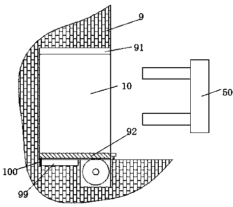
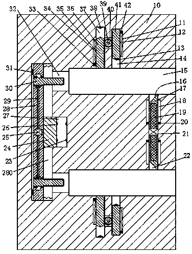
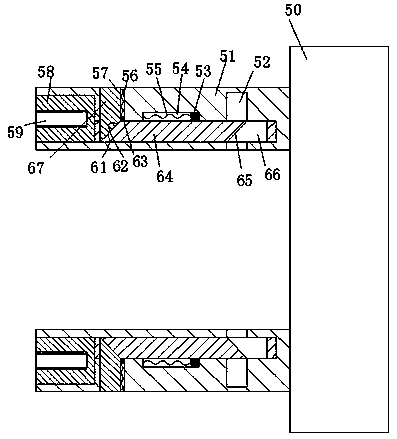
[0029] Such as Figure 1 to Figure 6 As shown, a new type of air dust removal device of the device of the present invention includes a housing chamber 91 that is arranged in the wall body 9 and opens to the right, and a power distribution cabinet 10 that is arranged in the housing chamber 91 through a push assembly and is connected with the dust collector electric Connected pin head 50, the upper and lower sides of the distribution cabinet 10...


PUM


Abstract

The invention discloses a novel air dust removal device. The device comprises a power distribution cabinet and a plug electrically connected with a dust remover, wherein the power distribution cabinetis arranged in a wall, has an opening facing rightwards and is arranged in an accommodating cavity through a push assembly, wherein plug-in slots with notches facing rightwards are vertically and symmetrically formed in the power distribution cabinet, first sliding chutes which are located between the two plug-in slots and have the notches facing the plug-in slots are vertically and symmetricallyformed in the power distribution cabinet, a first electrical motor is mounted between the two first sliding chutes, first sliding arms are glidingly mounted in the first sliding chutes, first obliquesurfaces facing the end surfaces of the plug-in slots are arranged on the first sliding arms, first spiral slots with notches facing the first motor are formed in the first sliding arms, first spiralrods in power connection with the first electric motor are mounted in the first spiral slots in a thread fit manner, and second sliding chutes and third sliding chutes which have notches facing the plug-in slots are formed in the end walls, far away from the first sliding chutes, of the plug-in slots.

Description

technical field [0001] The invention relates to the field of environmental dust removal, in particular to a novel air dust removal device. Background technique [0002] Air dust collectors are widely used in industrial production. They are mainly used for adsorption and dust removal of polluted gases generated during industrial production. However, due to the high power of these dust collectors, some factories are specially equipped with plug-in power supply for dust collectors. Power distribution cabinets, however, these power distribution cabinets have a single setting mode, and the internal conductive sheets are set relatively outside. This conductive sheet is easily touched by metal sheets or metal rods. Therefore, when people who lack safety awareness use metal sheets Or electric shock accidents are likely to occur when the rod is in contact with the conductive sheet; at the same time, the dust collector needs to move its position frequently during the dust removal op...

Claims


Application Information

Patent Timeline
Patent Type & Authority Applications(China)
IPC IPC(8): B03C3/02B03C3/34
CPCB03C3/02B03C3/34
Inventor 乐康
Owner 福州和信城电子科技有限公司
Why Eureka
Try Eureka