Operating method of equipment airborne multistage airbag cooperative shock absorber

A technique of buffering device and working method, which is applied in the direction of launching device, transportation and packaging, aircraft parts, etc. It can solve the problems of slow outward exhaust speed, airbag explosion, and limited effective buffering stroke, so as to achieve enhanced buffering effect and good buffering Effect, the effect of increasing the effective buffer stroke

Active Publication Date: 2018-07-27
CHANGSHA UNIVERSITY OF SCIENCE AND TECHNOLOGY
View PDF7 Cites 5 Cited by
  • Summary
  • Abstract
  • Description
  • Claims
  • Application Information

AI Technical Summary

Problems solved by technology

However, in the process of equipment airborne landing buffer, if the vent hole of the airbag buffer device is too large, there will be a problem that the airborne equipment will directly touch the ground; If the exhaust speed is too slow, the airbag will explode, which will cause fatal damage to the airborne equipment
[0006] In order to overcome the shortcoming that the single-chamber airbag cushioning device is easy to explode, a small part of the prior art has used the technical scheme of the double-chamber airbag cushioning device: as the patent "multi-stage airbag combined buffering device" with the publication number CN1923617A, but this multiple The combined cushioning device of the first-stage airbag adopts a nested structure, which results in a limited effective buffer stroke; as the patent "dual-chamber airbag cushioning device" with the publication number CN1923618A, although this airbag cushioning device adopts the top air chamber of the airbag and the base air However, there is no other buffer device between the top air chamber and the bottom air chamber of the airbag, which still results in a limited effective buffer stroke, and the top air chamber and the bottom air chamber of the airbag are two separate independent air chambers, resulting in two The air chamber cannot coordinately buffer the airborne equipment, so it cannot play a good buffering effect on the airborne equipment

Method used


Image

  • Operating method of equipment airborne multistage airbag cooperative shock absorber
  • Operating method of equipment airborne multistage airbag cooperative shock absorber
  • Operating method of equipment airborne multistage airbag cooperative shock absorber

Examples


Embodiment Construction

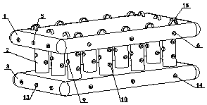
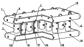
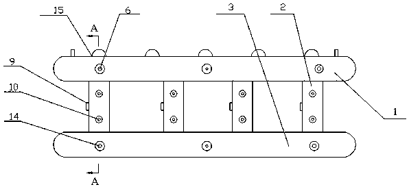
[0030] As shown in the figure: a working method equipped with an airborne multi-stage airbag cooperative buffer device, the multi-stage airbag cooperative buffer device includes an upper air bag 1, an air bag column 2 and a lower air bag 3; the present invention adopts an upper air bag 1, an air bag tube The column 2 and the lower airbag 3 are installed in a superimposed manner; the top of the upper airbag 1 is provided with a buckle device 15 to connect with the airborne equipment; the surface of the upper airbag 1 is provided with an upper airbag inflation valve 5, and the inside of the upper airbag 1 is the upper airbag chamber 4, and the upper airbag Ten upper airbag exhaust valves 6 are arranged on the surface of the upper airbag 1, and a joint exhaust valve 7 is arranged at the overlapping connection between the surface of the upper airbag 1 and the surface of each airbag column 2.

[0031] As shown in the figure: there are 12 airbag columns, and the airbag columns 2 are ...


PUM


Abstract

The invention discloses an operating method of an equipment airborne multistage airbag cooperative shock absorber. The multistage airbag cooperative shock absorber comprises an upper airbag, an airbagtube column and a lower airbag. In an equipment airborne landing process, the upper airbag can discharge gases and relieve pressure outside by virtue of an upper airbag exhaust valve, gases can be discharged to the airbag tube column by virtue of a combined exhaust valve I, and the airbag tube column expands to realize first-stage shock absorption; the airbag tube column can discharge gases and relieve pressure outside by virtue of an airbag tube column exhaust valve, gases can be discharged to the lower airbag by virtue of a combined exhaust valve II, and the lower airbag expands to realizesecond-stage shock absorption; the lower airbag can discharge gases and relieve pressure outside by virtue of a lower airbag exhaust valve to realize third-stage shock absorption; after equipment airborne safe landing, the airbag device can be vented and is convenient to contain and store. According to the multistage shock absorption method of the multistage airbag cooperative shock absorber, airborne equipment can be prevented from directly contacting with the ground, multistage release of the pressure inside the airbag can also be realized, airbag blasting is avoided, and safe landing of theairborne equipment is ensured.

Description

technical field [0001] The invention relates to the field of equipment airborne safety protection, in particular to a working method of equipped with an airborne multi-stage airbag cooperative buffer device. Background technique [0002] Due to its light weight and good energy absorption effect, the airbag cushioning device has been widely used in technical fields such as equipment airborne, drone recovery, space return, etc., and has become an important part of equipment safety. [0003] In the actual equipment airborne landing process, the cushioning effect of the existing airbag cushioning device is limited, and there are the following problems. [0004] Most of the existing landing airbag cushioning devices for airborne equipment use a single-chamber airbag cushioning device with a single structure, resulting in a single and limited setting of the initial cushioning pressure of the air chamber, resulting in limited cushioning effect. [0005] The existing single-chamber...

Claims


Application Information

Patent Timeline
Patent Type & Authority Applications(China)
IPC IPC(8): B64D1/14
CPCB64D1/14
Inventor 刘鑫董建业张志勇吴迪王昕宇张远洋
Owner CHANGSHA UNIVERSITY OF SCIENCE AND TECHNOLOGY
Why Eureka
Try Eureka