


Quick Research
Generate reliable direction feasibility study reports for your R&D in just a few steps.

Technical Q&A
Discover and master advanced knowledge NOW. Basics, ideas, possibilities, all at once.

Find Solutions
As an expert in R&D theories, this can generate solutions to your technical problems instantly.

Evaluate Feasibility
Analyze your overall solution with one click, know your potential R&D risks in advance.

Monitor Landscape
Get weekly tech updates, stay abreast of the latest tech innovations and key insights.
Spray nozzle arrangements
A nozzle device, nozzle technology, applied in the direction of spray device, spray device, distribution device, etc., can solve problems such as large capacity
- Summary
- Abstract
- Description
- Claims
- Application Information
AI Technical Summary
Problems solved by technology
Method used
Image

Examples
Embodiment Construction
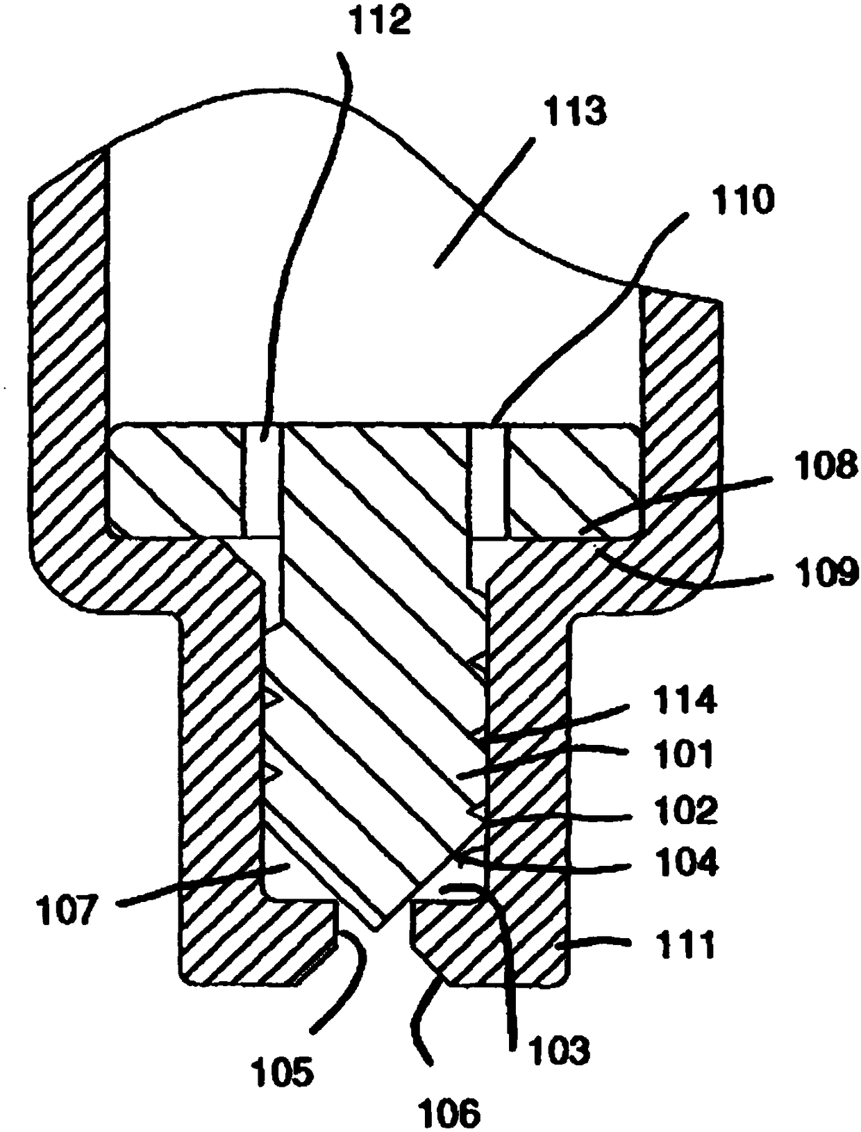
[0049] The atomized spray produced by the shaped pushrod 101 in the shaped orifice can be produced as a continuous or pulsed spray by a number of different but similar configurations. figure 1 The most basic configuration shown includes a stationary pushrod 101 with a threaded portion 102 having a circumferential groove 114 which causes fluid to flow around the pushrod 101 through the groove 114 and between the pushrod 101 and An interference fit is formed between the chamber walls 104 . The push rod 101 cannot move and is positioned such that there is a small circumferential gap 103 between the push rod 101 and the parallel side tubular portion 105 or the upstream end of the outlet orifice. Downstream of this, a preferred (but not exclusive) arrangement is to have an outwardly tapered tapered portion 106 in the nozzle exit hole. Upstream pushrod flange 108 abuts against annular flange 109 of nozzle body 111 having openings 110 and 112 which allow fluid to pass from nozzle in...
PUM
 Abstract
Description
Claims
Application Information
 - R&D Engineer
- R&D Manager
- IP Professional
- Industry Leading Data Capabilities
- Powerful AI technology
- Patent DNA Extraction
Browse by: Latest US Patents, China's latest patents, Technical Efficacy Thesaurus, Application Domain, Technology Topic, Popular Technical Reports.
© 2024 PatSnap. All rights reserved.Legal|Privacy policy|Modern Slavery Act Transparency Statement|Sitemap|About US| Contact US: help@patsnap.com