
Systems and methods for visual object tracking

A technology of target objects and image frames, applied in the field of systems and methods for visual target tracking, capable of solving problems such as reducing the utility of aircraft

Active Publication Date: 2021-08-17
SZ DJI TECH CO LTD
View PDF6 Cites 0 Cited by
  • Summary
  • Abstract
  • Description
  • Claims
  • Application Information

AI Technical Summary

Problems solved by technology

this limited tracking capability may reduce the vehicle's usefulness in some applications

Method used


Image

  • Systems and methods for visual object tracking
  • Systems and methods for visual object tracking
  • Systems and methods for visual object tracking

Examples


Embodiment Construction

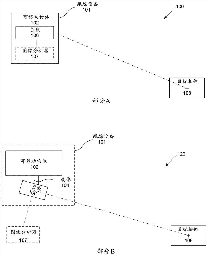
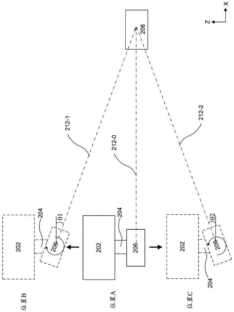
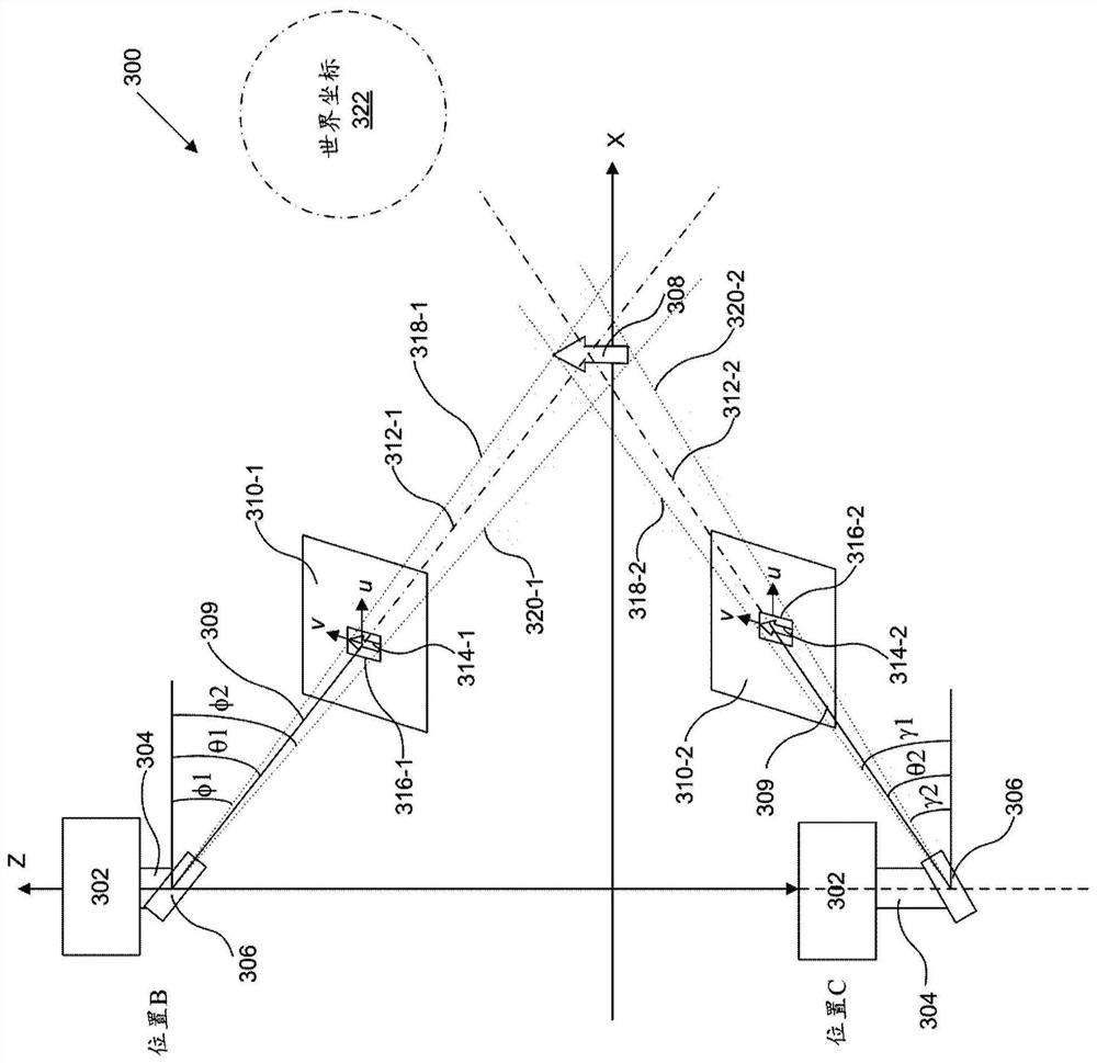
[0041] The systems, methods and devices described herein allow target objects to be tracked with high precision and accuracy. This can improve the tracking capabilities of the tracking device. For example, the systems, methods and devices described can be used to accurately track a moving target object while the tracking device is in a different spatial arrangement relative to the target object. A tracking device may include a movable object configured to track and / or follow a target object. The movable object can carry a payload that includes imaging equipment that provides visual tracking capabilities. In some embodiments, the imaging device can be rigidly attached to the movable object such that the translational and / or rotational movements of the movable object and the imaging device are the same about one or more axes. Optionally, the imaging device may be integrated into the housing of the movable object to form part of the movable object. In other embodiments, the im...


PUM


Abstract

The present disclosure provides a method for controlling a movable object to track a target object. The method may include determining a change in one or more features between a first image frame and a second image frame, wherein the one or more features are associated with the target object, and wherein at different points in time capturing the first image frame and the second image frame; and adjusting the movable movement of objects.

Description

Background technique [0001] In some surveillance, reconnaissance, and exploration tasks for real-world applications, it may be necessary to detect and track moving target objects. A movable object carrying a payload (eg, an aircraft carrying a camera) can be used to track a target object using, for example, visual tracking methods. However, existing visual tracking methods often may not take into account the spatial arrangement of the vehicle and / or camera relative to the target. In some cases, one or more operators may have to manually select the target object to track and manually control the aircraft and / or cameras to track the moving target. This limited tracking capability may reduce the vehicle's usefulness in certain applications. Contents of the invention [0002] There is a need to improve existing methods for visual tracking of moving objects. Improved tracking capabilities may enable a movable object carrying an imaging device to accurately track a target even ...

Claims


Application Information

Patent Timeline
Patent Type & Authority Patents(China)
IPC IPC(8): G05D1/12G06F17/10
CPCG05D1/0808G05D1/101B64U2101/30B64U30/20B64U10/13G05D1/0094B64U2201/10B64U2201/20B64U2101/64G06T7/74G06T7/248
Inventor 钱杰赵从封旭阳
Owner SZ DJI TECH CO LTD
Learn More