
Concave die with righting structure

A technology of concave die and centering sleeve, which is used in manufacturing tools, forging/pressing/hammer devices, forging/pressing/hammering machinery, etc. Material efficiency, ensure accurate clamping effect

Inactive Publication Date: 2018-08-03
江苏理研科技股份有限公司
View PDF5 Cites 1 Cited by
  • Summary
  • Abstract
  • Description
  • Claims
  • Application Information

AI Technical Summary

Problems solved by technology

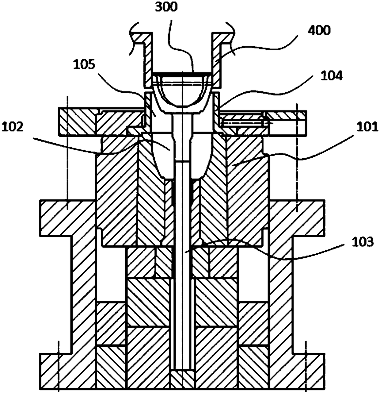
[0005] The concave die in the prior art has the following defects. When the upper end of the forging 300 protrudes from the centralizing sleeve 104, a gap appears between the forging 300 and the inner wall of the centralizing sleeve 104, thereby causing the forging 300 to tilt (stabilizing failure)
It makes it difficult for the robot gripper 400 to precisely clamp the forging 300, reducing the efficiency of material return

Method used


Image

  • Concave die with righting structure
  • Concave die with righting structure
  • Concave die with righting structure

Examples


Embodiment Construction

[0016] In order to make the above objects, features and advantages of the present invention more comprehensible, the present invention will be further described in detail below in conjunction with the accompanying drawings and specific embodiments.

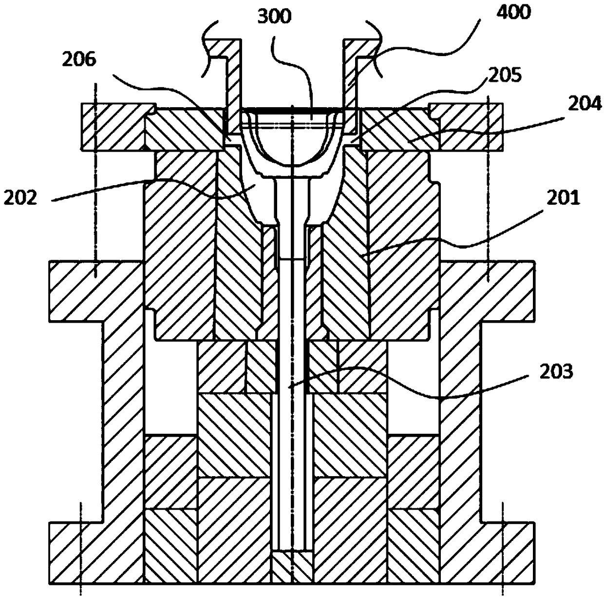
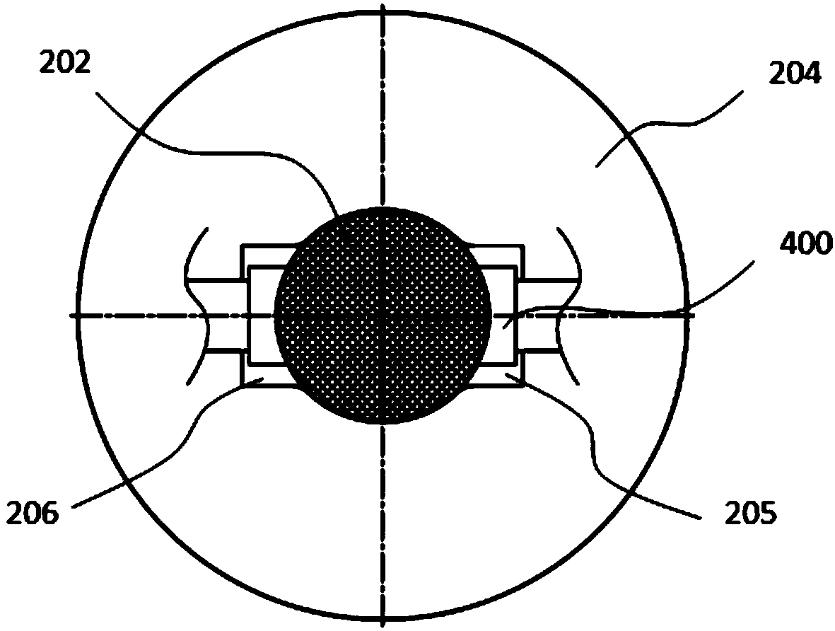
[0017] Such as Figure 2 to Figure 4 As shown, in a specific embodiment, the present invention provides a die 200 with a centralizing structure, which includes a die body 201 , a centralizing sleeve 204 , and a stripping rod 203 and other components.

[0018] A die cavity 202 is formed on the upper part of the die body 201 . In this embodiment, the upper opening of the cavity 202 of the female die is circular.

[0019] The centralizing sleeve 204 is connected to the upper surface of the die body 201 , and a guide channel is formed in the centralizing sleeve 204 . The guide passage includes a circular central hole 205, which communicates with the die cavity 202 and is coaxially arranged with the die cavity 202, and the aperture s...


PUM


Abstract

The invention provides a concave die with a righting structure. The concave die with the righting structure comprises a concave die body and a righting sleeve, wherein a concave die cavity is formed in the upper portion of the concave die body; and the righting sleeve is connected to the upper end face of the concave die body, a guide channel is formed in the righting sleeve and comprises a central hole, the central hole communicates with the concave die cavity and is coaxial with the concave die cavity, the shape and size of the central hole are consistent with those of an opening of the upper end of the concave die cavity, and the inner walls of the left side and the right side of the central hole are concaved outwards to form two clamping grooves symmetrical about the central hole. Therighting sleeve is connected to the upper end face of the concave die with the righting structure, and the clamping grooves are formed in the righting sleeve. Compared with a concave die with a righting structure in the prior art, the concave die with the righting structure can achieve righting of a forged piece, thereby guaranteeing that the forged piece is accurately clamped by a clamping jaw ofa robot, and improving material returning efficiency.

Description

technical field [0001] The invention relates to the field of forging auto parts, in particular to a concave die with a supporting structure. Background technique [0002] After the forging is extruded in the mold, the ejector rod pushes the forging out of the cavity of the die, and then the robot gripper grips the forging to complete the ejection. [0003] Such as figure 1 As shown, in the prior art, a die with a centering structure generally includes a die body 101, a die cavity 102 is formed on the upper part of the die body 101, and a return material is provided below the die cavity 102. Rod 103 . A centralizing sleeve 104 is connected to the upper end surface of the die body 101 . The centering sleeve 104 is formed with a guide hole 105 coaxial with the die cavity 102 , the shape and size of the guide hole 105 are consistent with the shape and size of the upper opening of the die cavity 102 . [0004] Therefore, after the forging 300 enters the guide hole 105 through...

Claims


Application Information

Patent Timeline
Patent Type & Authority Applications(China)
IPC IPC(8): B21J13/02B21J13/14B21J13/10
CPCB21J13/02B21J13/10B21J13/14
Inventor 季成蔡冰黄荣陈爱芬朱亚萍
Owner 江苏理研科技股份有限公司
Learn More