Adjustable vibration cylinder structure

A vibrating cylinder, adjustable technology, applied in the direction of grinding machine parts, metal processing equipment, grinding/polishing equipment, etc., can solve the problems of low polishing efficiency and long time consumption

Pending Publication Date: 2018-08-03
蔡惠文
View PDF6 Cites 0 Cited by
  • Summary
  • Abstract
  • Description
  • Claims
  • Application Information

AI Technical Summary

Problems solved by technology

[0002] Vibration polishing is to drive the eccentric wheel connected with the power output shaft of the drive motor to rotate rapidly and hit the vibrating cylinder to make the vibrating cylinder vibrate continuously. The vibrating cylinder drives the hardware parts and abrasives in the vibratin

Method used


Image

  • Adjustable vibration cylinder structure
  • Adjustable vibration cylinder structure
  • Adjustable vibration cylinder structure

Examples


Embodiment Construction

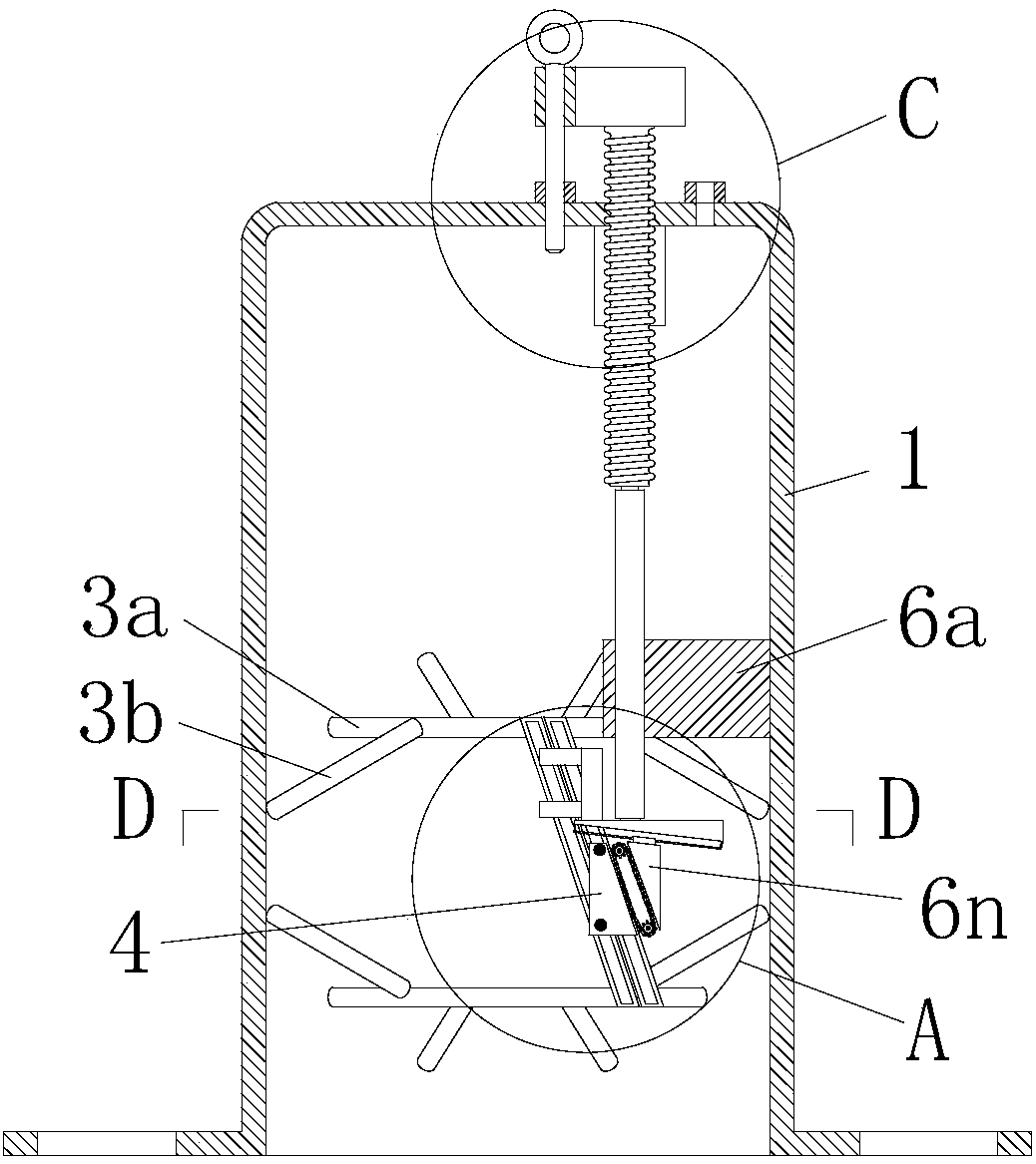
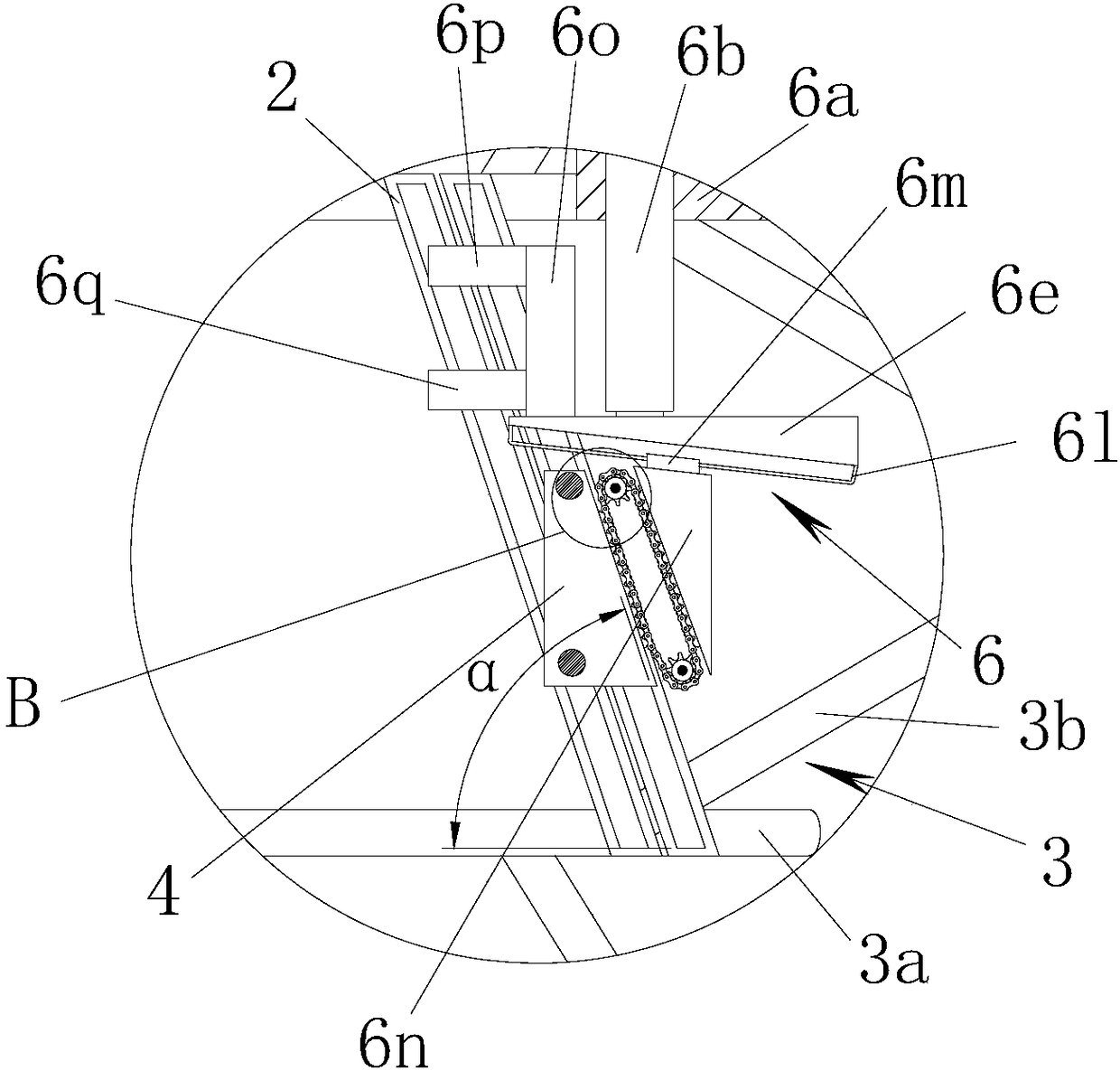
[0022] Refer to Figure 1 to Figure 7 As shown, an adjustable vibrating cylinder structure of the present invention includes a single-side open vibrating cylinder 1. The vibrating cylinder 1 is inclined and provided with two sets of vibration transmission grooves 2 opposite to each other. The two sets of vibration transmission grooves 2 respectively pass The corresponding vibration conduction fixing frame 3 is connected to the inner wall of the vibration cylinder 1; a vibration seat 4 is provided in the vibration cylinder 1, and the vibration seat 4 is connected to the vibration conduction groove 2 through a vibration rod 5. The included angle α between the vibration conducting groove 2 and the horizontal plane is 65-80°. Reasonable included angle can effectively produce and transmit vibration with the vibration base. The two ends of the vibrating rod 5 are provided with limit balls, and the limit balls are arranged in the vibration transmission groove 2. The vibration base 4...


PUM


Abstract

The invention discloses an adjustable vibration cylinder structure and belongs to the technical field of building construction. The adjustable vibration cylinder structure is technically characterizedby comprising a vibration cylinder with a single edge being opened, wherein two vibration conduction grooves are obliquely and oppositely arranged in the vibration cylinder, and the two vibration conduction grooves are connected with the inner wall of the vibration cylinder through corresponding vibration conduction fixing frames; the vibration cylinder is internally provided with a vibration base, and the vibration base is connected with the vibration conduction grooves through vibration rods; the included angle alpha between each vibration conduction groove and the horizontal face is 65 degrees-80 degrees; the vibration base corresponds to an external vibration drive mechanism; and the vibration base is connected with a first lifting adjusting mechanism. The adjustable vibration cylinder structure is compact in structure and good in using effect and is used for a vibration device.

Description

Technical field [0001] The invention relates to a vibrating cylinder structure, more specifically, to an adjustable vibrating cylinder structure. Background technique [0002] Vibration polishing is to drive the eccentric wheel connected to the power output shaft of the drive motor to quickly rotate and hit the vibrating cylinder to make the vibrating cylinder continue to vibrate. The vibrating cylinder drives the hardware parts and abrasives in the vibrating cylinder to rub to remove paint from the hardware parts. In the existing technology, the vibration intensity of the vibrating polishing equipment is the same for the effects of surface contamination, oxide layer and scratches, which not only makes the polishing efficiency low but also takes a long time. Summary of the invention [0003] The purpose of the present invention is to provide an adjustable vibrating cylinder structure with compact structure and good use effect in view of the above-mentioned shortcomings of the prio...

Claims


Application Information

Patent Timeline
IPC IPC(8): B24B41/00
CPCB24B41/00
Inventor 蔡惠文
Owner 蔡惠文
Why Eureka
Try Eureka