
High-accuracy burr polishing mechanism used between gear teeth

A gear teeth, high-precision technology, applied in the direction of grinding racks, grinding machine parts, belts/chains/gears, etc., can solve the problems of not meeting the needs of manufacturers, low cleaning efficiency, and reduced product quality. Improve the polishing effect, improve the practicality and improve the stability

Inactive Publication Date: 2021-06-25
JIANGSU SECURITY TECH CARRER ACADEMY
View PDF8 Cites 1 Cited by
  • Summary
  • Abstract
  • Description
  • Claims
  • Application Information

AI Technical Summary

Problems solved by technology

[0003] Nowadays, gears are widely used in mechanical systems as commonly used transmission parts, and gears are indispensable transmission parts. At the same time, in some occasions where the transmission accuracy is relatively high, in order to ensure the reliability and stability of the transmission, it is necessary to use High-precision gears, and during the production process of high-precision gears, there will be burrs between the teeth of the gears, so it needs to be removed by polishing, and the traditional burr removal method is usually done manually, because the workpiece is usually relatively large Small, manual cleaning is often easy to clean incompletely, and manual deburring is not only time-consuming and labor-intensive, but also low in cleaning efficiency, and also reduces the quality of the product, so there are deficiencies and cannot meet the needs of manufacturers. Therefore, it is necessary to further improve

Method used


Image

  • High-accuracy burr polishing mechanism used between gear teeth
  • High-accuracy burr polishing mechanism used between gear teeth
  • High-accuracy burr polishing mechanism used between gear teeth

Examples


Embodiment Construction

[0023] The present invention will be further described below in conjunction with accompanying drawing:

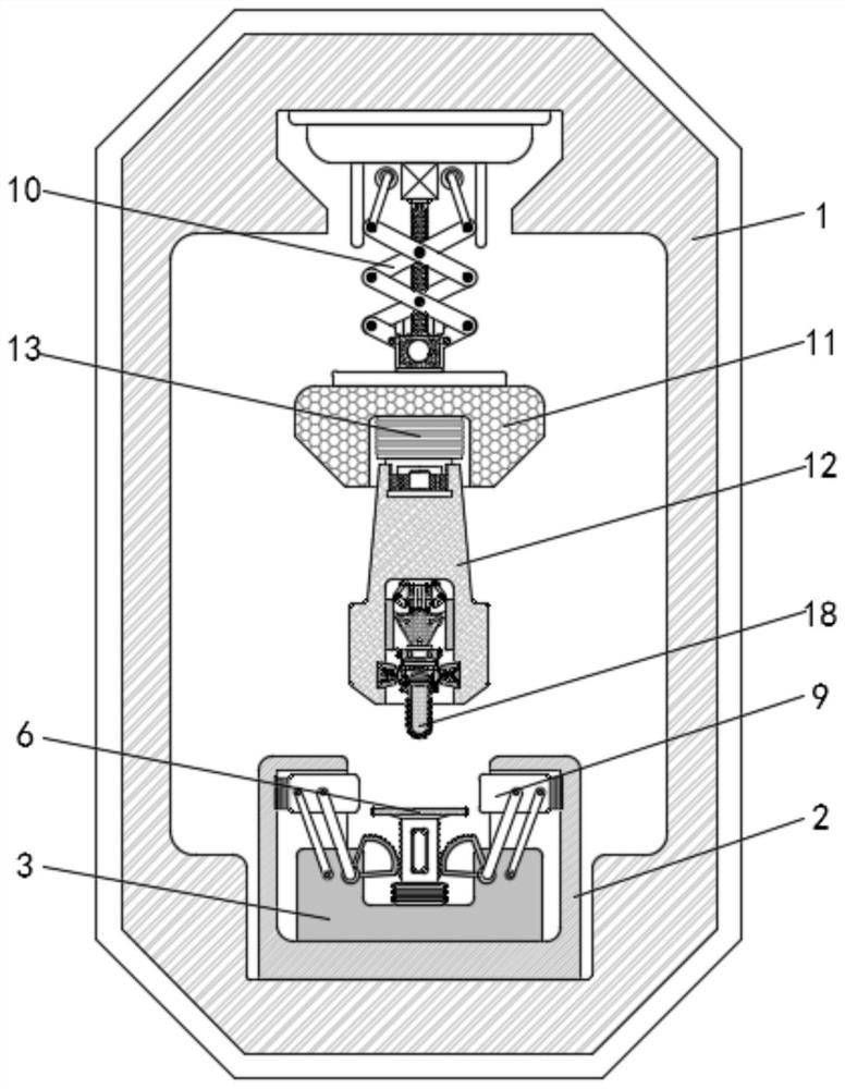
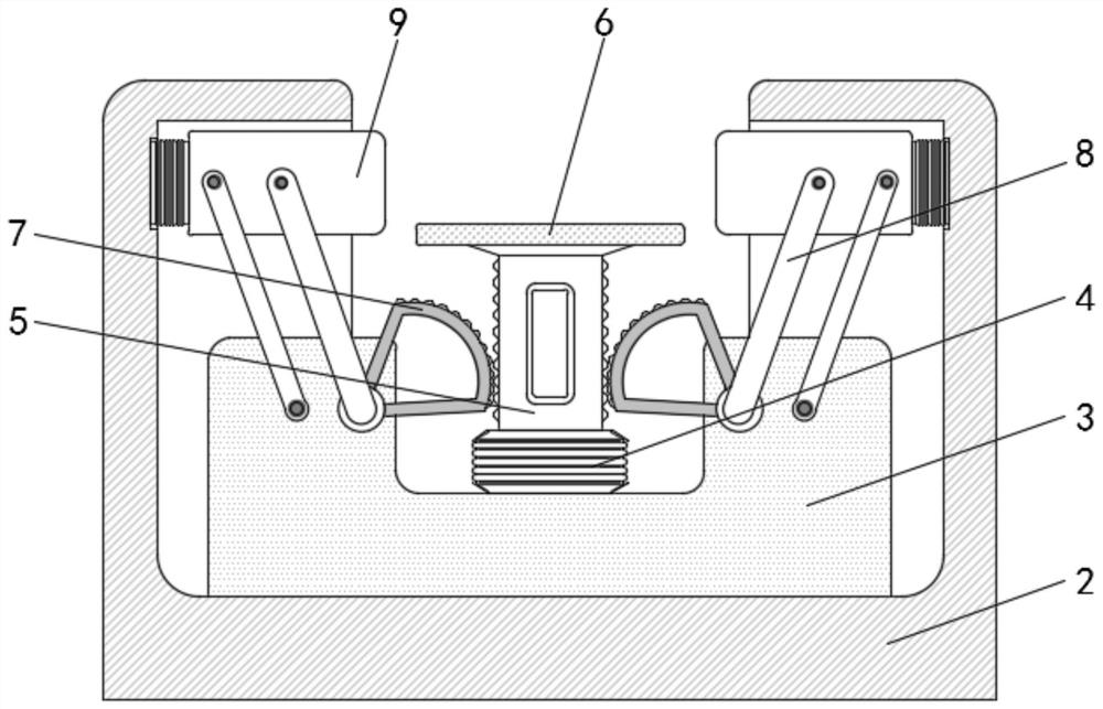
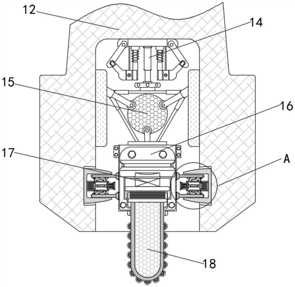
[0024] as attached figure 1 To attach Figure 4 Shown:

[0025] The invention provides a high-precision gear interdental burr polishing mechanism, which includes a main body 1, a housing 2 is installed at the bottom of the inner wall of the main body 1, and a fixed base 3 is installed inside the housing 2, and the inside of the fixed base 3 A support air cushion 4 is installed, a support column 5 is fixedly installed on the upper side of the support air cushion 4, a bearing platform 6 is fixedly installed on the upper end of the support column 5, racks are arranged on the left and right sides of the support column 5, and the support column 5 utilizes a toothed The bar is meshed with the movable toothed plate 7, and the movable toothed plate 7 is movably equipped with a movable connecting rod 8, and the upper end of the movable connecting rod 8 is movably installed with a ...


PUM


Abstract

The invention provides a high-accuracy burr polishing mechanism used between gear teeth. The high-accuracy burr polishing mechanism comprises a main body, wherein a shell is mounted at the bottom of the inner wall of the main body; a fixed base is mounted in the shell; a support air cushion is mounted in the fixed base; supporting columns are fixedly mounted on the upper side of the support air cushion; a bearing platform is fixedly mounted at the upper ends of the supporting columns; and racks are arranged on the left side and the right side of the each supporting column. According to the high-accuracy burr polishing mechanism used between the gear teeth disclosed by the invention, in a machining process of a polishing head, due to the phenomenon that the polishing head on the polishing mechanism is shaken because of uncontrollable reasons, a correction mechanism is driven through a fixed rod to contact with the polishing mechanism; and by utilizing the correction mechanism, the shaking which occurs on the polishing mechanism can be absorbed and counterbalanced, so that correction of the polishing mechanism is realized, and thus, resetting of the polishing mechanism is further completed, and the polishing effect of the polishing mechanism on gears is further improved; and moreover, the equipment has a simple structure and is safe and reliable.

Description

technical field [0001] The invention belongs to the technical field of gear burr polishing, in particular to a high-precision gear interdental burr polishing mechanism. Background technique [0002] Nowadays, the development of machinery is inseparable from gears, the most critical parts, no matter where. The precision of gears directly affects the precision of manufactured products. Therefore, my country now pays more and more attention to the manufacture of high-precision gears. Gear transmission is Refers to the device that transmits motion and power by a gear pair. It is one of the most widely used mechanical transmission methods for various equipment. It has the advantages of accurate transmission, high transmission efficiency, compact structure, reliable operation, and long service life. High-precision gears are used for It is suitable for occasions where high transmission precision is required. [0003] Nowadays, gears are widely used in mechanical systems as commonly ...

Claims


Application Information

Patent Timeline
Patent Type & Authority Applications(China)
IPC IPC(8): B24B9/00B24B41/02B24B41/04B24B41/00B24B41/06B24B27/00B23F19/00
CPCB24B9/00B24B41/02B24B41/04B24B41/007B24B41/06B24B27/0015B23F19/00
Inventor 彭红梅陈亚
Owner JIANGSU SECURITY TECH CARRER ACADEMY
Learn More