Vibration cylinder structure for vibration polishing equipment

A vibrating cylinder and equipment technology, applied in grinding/polishing equipment, machine tools suitable for grinding workpiece edges, metal processing equipment, etc., can solve the problems of long time consumption and low polishing efficiency.

Pending Publication Date: 2018-08-24
蔡惠文
View PDF0 Cites 0 Cited by
  • Summary
  • Abstract
  • Description
  • Claims
  • Application Information

AI Technical Summary

Problems solved by technology

[0002] Vibration polishing is to drive the eccentric wheel connected with the power output shaft of the drive motor to rotate rapidly and hit the vibrating cylinder to make the vibrating cylinder vibrate continuously. The vibrating cylinder drives the hardware parts and abrasives in the vibrating cylinder to rub to remove the paint on the hardware parts. Surface pollution, oxide layer and scratches, in the existing technology, the vibration intensity of the vibration polishing equipment is the same, which not only makes the polishing efficiency low but also takes a long time

Method used


Image

  • Vibration cylinder structure for vibration polishing equipment
  • Vibration cylinder structure for vibration polishing equipment
  • Vibration cylinder structure for vibration polishing equipment

Examples


Embodiment Construction

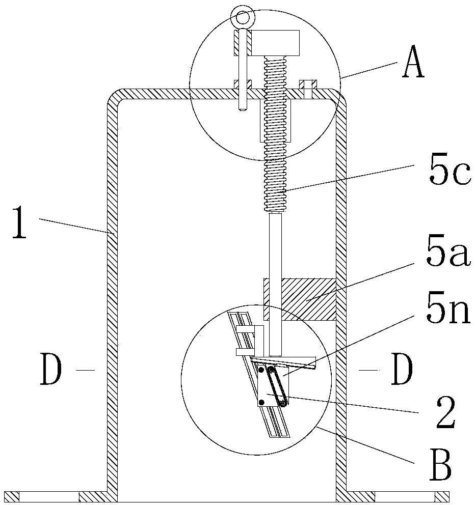
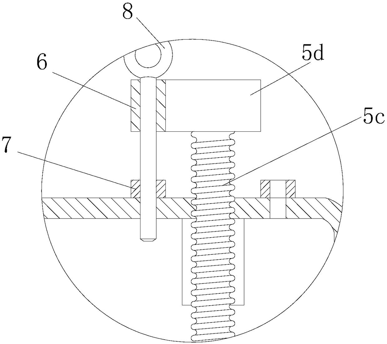
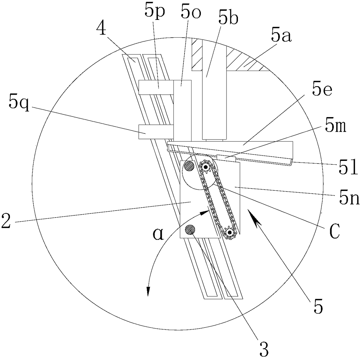
[0022] refer to Figure 1 to Figure 7 As shown, a vibrating tube structure used for vibrating polishing equipment of the present invention includes a vibrating tube 1 with one side open, and a vibrating seat 2 is arranged inside the vibrating tube 1, and the vibrating seat 2 is connected to the vibrating tube through a vibrating rod 3. Cartridge 1 is connected. The vibration base 2 corresponds to the external vibration driving mechanism. The external vibration driving mechanism can be composed of a driving motor, an eccentric wheel connected with the power output shaft of the driving motor, and an induction turntable connected with the eccentric wheel through a rotating shaft. The vibration seat corresponds to the eccentric wheel.

[0023] The vibrating tube 1 is provided with vibrating conduction grooves 4 which match with the two ends of the vibrating rod 3 . The included angle α between the two groups of vibration conducting grooves 4 and the horizontal plane is 65-80°. ...


PUM


Abstract

The invention discloses a vibration cylinder structure for vibration polishing equipment, and belongs to the technical field of part machining. The structure comprises a vibration cylinder opened on one edge; a vibration base is arranged in the vibration cylinder, and is connected with the vibration cylinder through a vibration rod; the vibration base is corresponding to an external vibration driving mechanism; vibration transfer grooves cooperating with the two ends of the vibration rod are aslant arranged in the vibration cylinder; when the vibration rod slides along the vibration transfer grooves, the two ends of the vibration rod are always positioned in the vibration transfer grooves; included angles alpha between the two sets of vibration transfer grooves and the horizontal plane are65-80 degrees; and the vibration base is connected with a first lifting adjusting mechanism. The invention aims to provide the vibration cylinder structure for the vibration polishing equipment, which is compact in structure and excellent in use effect; and the vibration cylinder structure is used for the vibration polishing equipment.

Description

technical field [0001] The present invention relates to a vibrating cylinder structure, and more specifically, relates to a vibrating cylinder structure used for vibrating polishing equipment. Background technique [0002] Vibration polishing is to drive the eccentric wheel connected with the power output shaft of the drive motor to rotate rapidly and hit the vibrating cylinder to make the vibrating cylinder vibrate continuously. The vibrating cylinder drives the hardware parts and abrasives in the vibrating cylinder to rub to remove the paint on the hardware parts. The effect of surface pollution, oxide layer and scratches, in the existing technology, the vibration intensity of the vibration polishing equipment is the same, which not only makes the polishing efficiency low but also takes a long time. Contents of the invention [0003] The object of the present invention is to provide a vibrating barrel structure of a vibrating polishing device with a compact structure and...

Claims


Application Information

Patent Timeline
Patent Type & Authority Applications(China)
IPC IPC(8): B24B31/06B24B31/12
CPCB24B31/06B24B31/12
Inventor 蔡惠文
Owner 蔡惠文
Why Eureka
Try Eureka