Iron sheet cutting equipment for battery box machining

A technology for cutting equipment and battery boxes, which is applied to metal processing equipment, metal sawing equipment, manufacturing tools, etc., can solve the problems that iron sheets are easy to scratch people, time-consuming and labor-intensive, etc., and achieve low manufacturing cost, convenient use, and simple operation Effect

Inactive Publication Date: 2018-08-07
史志成
View PDF4 Cites 3 Cited by
  • Summary
  • Abstract
  • Description
  • Claims
  • Application Information

AI Technical Summary

Problems solved by technology

[0005] In order to overcome the need to cut the iron sheet when the battery box is processed, the present invention uses a manual cutting wheel to cut the iron sheet manually. Manually holding the cutting wheel to cut the iron sheet is not only time-consuming and laborious. And the shortcoming that the sharp iron sheet is easy to scratch people when cutting, the technical problem to be solved by the present invention is to provide a kind of machine instead of manual battery box processing iron sheet cutting equipment

Method used


Image

  • Iron sheet cutting equipment for battery box machining
  • Iron sheet cutting equipment for battery box machining
  • Iron sheet cutting equipment for battery box machining

Examples


Embodiment 1

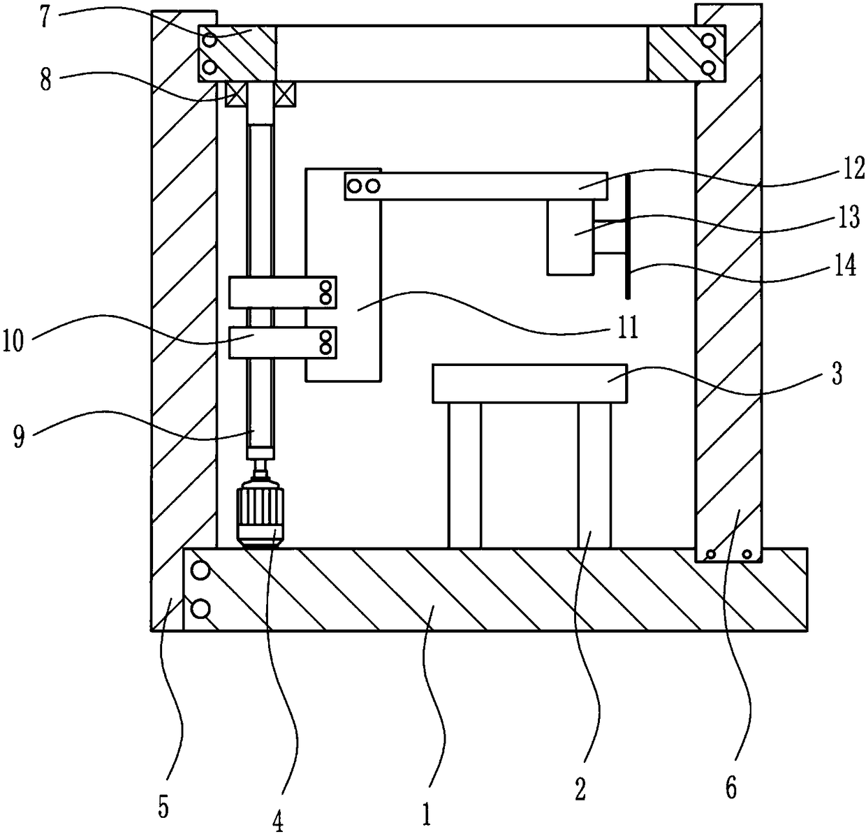
[0024] A battery box processing iron sheet cutting equipment, such as Figure 1-4 As shown, it includes a base 1, a first pole 2, a support plate 3, a first motor 4, a first bracket 5, a second bracket 6, a third bracket 7, a bearing 8, a screw 9, a nut 10, and a fixing plate 11 , the fourth support 12, the second motor 13 and the saw gear 14 are fixedly connected with two first poles 2 on the base 1, and are fixedly connected with a support plate 3 at the tops of the two first poles 2, and on the base 1 The first motor 4 is fixedly connected to the upper left side of the base 1, the first bracket 5 is fixedly connected to the left end of the base 1, the second bracket 6 is fixedly connected to the upper right side of the base 1, and the upper left side of the first bracket 5 is fixed. A third bracket 7 is connected, and the right end of the third bracket 7 is fixedly connected with the second bracket 6, and a bearing 8 is fixedly connected to the left side below the third bra...

Embodiment 2

[0026] A battery box processing iron sheet cutting equipment, such as Figure 1-4 As shown, it includes a base 1, a first pole 2, a support plate 3, a first motor 4, a first bracket 5, a second bracket 6, a third bracket 7, a bearing 8, a screw 9, a nut 10, and a fixing plate 11 , the fourth support 12, the second motor 13 and the saw gear 14 are fixedly connected with two first poles 2 on the base 1, and are fixedly connected with a support plate 3 at the tops of the two first poles 2, and on the base 1 The first motor 4 is fixedly connected to the upper left side of the base 1, the first bracket 5 is fixedly connected to the left end of the base 1, the second bracket 6 is fixedly connected to the upper right side of the base 1, and the upper left side of the first bracket 5 is fixed. A third bracket 7 is connected, and the right end of the third bracket 7 is fixedly connected with the second bracket 6, and a bearing 8 is fixedly connected to the left side below the third bra...

Embodiment 3

[0029] A battery box processing iron sheet cutting equipment, such as Figure 1-4As shown, it includes a base 1, a first pole 2, a support plate 3, a first motor 4, a first bracket 5, a second bracket 6, a third bracket 7, a bearing 8, a screw 9, a nut 10, and a fixing plate 11 , the fourth support 12, the second motor 13 and the saw gear 14 are fixedly connected with two first poles 2 on the base 1, and are fixedly connected with a support plate 3 at the tops of the two first poles 2, and on the base 1 The first motor 4 is fixedly connected to the upper left side of the base 1, the first bracket 5 is fixedly connected to the left end of the base 1, the second bracket 6 is fixedly connected to the upper right side of the base 1, and the upper left side of the first bracket 5 is fixed. A third bracket 7 is connected, and the right end of the third bracket 7 is fixedly connected with the second bracket 6, and a bearing 8 is fixedly connected to the left side below the third brac...


PUM


Abstract

The invention relates to cutting equipment, in particular to iron sheet cutting equipment for battery box machining. According to the iron sheet cutting equipment for battery box machining, manual work is replaced with machinery. The iron sheet cutting equipment for battery box machining comprises a base, first supporting rods, a supporting plate, a first motor, a first support, a second support,a third support, a bearing, a screw, nuts, a fixing plate, a fourth support and the like, wherein the two first supporting rods are fixedly connected to the base, the supporting plate is fixedly connected to the top ends of the two first supporting rods, the first motor is fixedly connected to the left side of the upper portion of the base, and the first support is fixedly connected to the left end of the base. The iron sheet cutting equipment for battery box machining has the advantages of being capable of achieving the automatic cutting function, capable of achieving the automatic iron sheetfixing function, convenient to use, safe in operation, simple to operate, low in manufacturing cost and the like.

Description

technical field [0001] The invention relates to a cutting device, in particular to a cutting device for processing iron sheet of a battery box. Background technique [0002] Cutting is a physical action. Cutting in a narrow sense refers to cutting objects (such as food, wood and other objects with low hardness) with sharp tools such as knives; cutting in a broad sense refers to using tools, such as machine tools, flames, etc. Objects are broken under the action of pressure or high temperature. In mathematics, there is also a "cutting line", which refers to a straight line that can divide a plane into several parts. Cutting plays an important role in people's production and life. [0003] When processing the battery box, it is necessary to cut the iron sheet. The existing cutting method is to use the manual cutting wheel to cut the iron sheet. Manually holding the cutting wheel to cut the iron sheet is not only time-consuming and laborious, but also when cutting Sharp iron ...

Claims


Application Information

Patent Timeline
Patent Type & Authority Applications(China)
IPC IPC(8): B23D47/04B23D47/08
CPCB23D47/04B23D47/08
Inventor 史志成秦静文张维洁
Owner 史志成
Why Eureka
Try Eureka