Eureka AIR delivers breakthrough ideas for toughest innovation challenges, trusted by R&D personnel around the world.

Automatic recognition equipment of intelligent door lock

An automatic identification, intelligent door lock technology, applied in building locks, lock applications, electric registration locks, etc., can solve the problems of real-time monitoring, the control center can not easily monitor key cards and door locks, security risks, etc. To achieve the effect of improving the safety of use, high safety and increasing safety

Inactive Publication Date: 2018-08-07
ZHENGZHOU WEIYIJIA ELECTRONICS TECH CO LTD
View PDF0 Cites 2 Cited by
  • Summary
  • Abstract
  • Description
  • Claims
  • Application Information

AI Technical Summary

Problems solved by technology

[0002] Smart door locks refer to locks that are different from traditional mechanical locks and are more intelligent in terms of user identification, security, and management, covering specific types of lock products such as fingerprint locks, electronic combination locks, electronic induction locks, networked locks, and remote control locks. The smart door lock has an automatic electronic induction locking system. When it automatically senses that the door is closed, the system will automatically lock. The smart door lock can open the door lock through fingerprints or touch screens or key cards. Authorized by the control center, it can be unlocked through fingerprints or Enter the password or key card on the touch screen to control the opening of the door lock, but this method cannot realize real-time monitoring. Once the key card is authorized, the control center cannot conveniently monitor the key card and door lock for a period of time. , there is a great security risk

Method used


Image

  • Automatic recognition equipment of intelligent door lock
  • Automatic recognition equipment of intelligent door lock

Examples


Embodiment Construction

[0019] The following will clearly and completely describe the technical solutions in the embodiments of the present invention with reference to the accompanying drawings in the embodiments of the present invention. Obviously, the described embodiments are only some, not all, embodiments of the present invention.

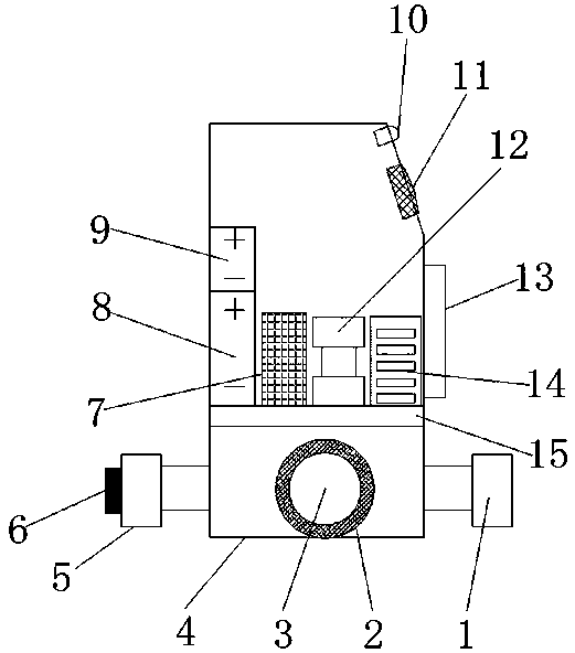
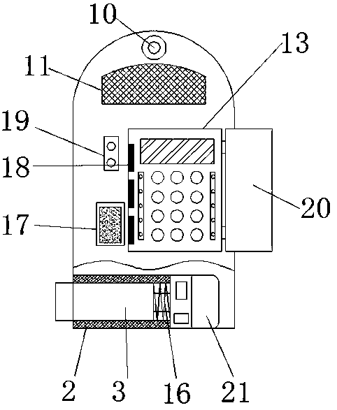
[0020] refer to Figure 1-2 , an intelligent door lock automatic identification device, including a lock case 4, a circular opening is opened on one side of the outer wall of the lock case 4, and a conduit 2 is sleeved on the inner wall of the circular opening, and a lock bolt 3 is sleeved on the inner wall of the conduit 2, and The outer wall of the conduit 2 away from the outer wall of the lock housing 4 is fixed with a push rod motor 21 by bolts, the output shaft of the push rod motor 21 is connected with the dead bolt 3, and the outer wall of the dead bolt 3 close to the push rod motor 21 is sleeved with a spring 16 One side of the outer wall of the lock case 4 i...


PUM


Abstract

The invention discloses automatic recognition equipment of an intelligent door lock. The automatic recognition equipment comprises a lock shell, wherein a round opening is formed in the outer wall ofone side of the lock shell, and a guide pipe is sleeved with the inner wall of the round opening; a lock tongue is sleeved with the inner wall of the guide pipe, and the outer wall of one side, separating from the outer wall of the lock shell, of the guide pipe is fixedly provided with a push-rod motor by a bolt; an output shaft of the push-rod motor is connected with the lock tongue, and the outer wall of one side, close to the push-rod motor, of the lock tongue is connected with a spring in a sheathing manner; an outer handle is fixed at the outer wall of one side of the lock shell by a bolt. The automatic recognition equipment disclosed by the invention has the beneficial effects that by addition of a fingerprint recognizer and a control panel with an electromagnet, dual authenticationcan be carried out, so that the safety of the intelligent door lock is improved; a camera and a storage device can monitor each person unlocking the door lock, and a standby power supply can be usedfor supplying power in power failure of a commonly-used power supply, so that the intelligent door lock is convenient in use and high in safety; the person opening a door can be monitored in real time, so that the use safety is greatly improved.

Description

technical field [0001] The invention relates to the technical field of intelligent door locks, in particular to an automatic identification device for intelligent door locks. Background technique [0002] Smart door locks refer to locks that are different from traditional mechanical locks and are more intelligent in terms of user identification, security, and management, covering specific types of lock products such as fingerprint locks, electronic combination locks, electronic induction locks, networked locks, and remote control locks. The smart door lock has an automatic electronic induction locking system. When it automatically senses that the door is closed, the system will automatically lock. The smart door lock can open the door lock through fingerprints or touch screens or key cards. Authorized by the control center, it can be unlocked through fingerprints or Enter the password or key card on the touch screen to control the opening of the door lock, but this method ca...

Claims


Application Information

Patent Timeline
Patent Type & Authority Applications(China)
IPC IPC(8): E05B47/00E05B17/18E05B17/22E05B17/00E05B17/10E05B45/06E05B49/00E05B15/10
CPCE05B47/0001E05B15/10E05B17/00E05B17/0083E05B17/10E05B17/145E05B17/183E05B17/22E05B45/061E05B47/026E05B49/00
Inventor 郭文
Owner ZHENGZHOU WEIYIJIA ELECTRONICS TECH CO LTD
Why Eureka
Eureka Blog
Learn More