Riveting and positioning device applied to T-shaped electric brake component

A technology of positioning device and electric switch, applied in the field of pressure riveting positioning device, can solve the problems such as the influence of product processing accuracy, punch wear, punch positioning and guiding function influence, etc.

Pending Publication Date: 2018-08-10
昆山仁硕机械制造有限公司
View PDF0 Cites 0 Cited by
  • Summary
  • Abstract
  • Description
  • Claims
  • Application Information

AI Technical Summary

Problems solved by technology

[0003] At present, it is mainly realized by stamping and riveting equipment, but the punch is prone to wear after a period of use, which affects the positioning and guiding functions of the punch, which may affect the processing accuracy of the product.

Method used


Image

  • Riveting and positioning device applied to T-shaped electric brake component
  • Riveting and positioning device applied to T-shaped electric brake component

Examples


Embodiment 1

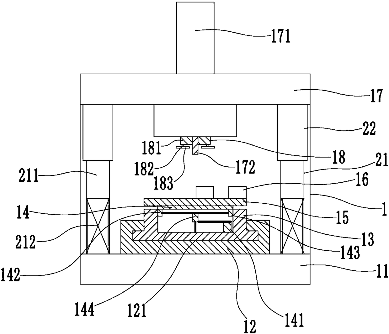
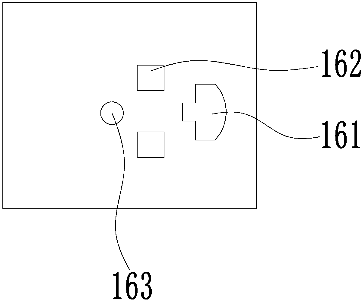
[0021] see Figure 1 to Figure 2 , the figure shows a pressure riveting positioning device applied to T-shaped electric brake parts provided by Embodiment 1 of the present invention, which includes a frame 1, a base 11 is provided on the bottom of the frame 1, and a mounting bracket is fixedly installed on the base 11. Plate 12, a chute 121 is opened on the mounting plate 12, a first positioning plate 13 is slidably connected in the chute 121, and a rotating shaft 14 is installed on the first positioning plate 13, and the rotating shaft 14 is connected to the eccentric shaft 141 in transmission, and the rotating shaft 14 is connected to There is a second positioning plate 15, the surface of the second positioning plate 15 is provided with a positioning portion 16, the movable plate 17 movable in the vertical direction is installed on the frame 1, the movable plate 17 is connected with the driving cylinder 171, and the bottom of the movable plate 17 is equipped with The rivet p...

Embodiment 2

[0024] see Figure 1 to Figure 2 , the figure shows a riveting positioning device applied to T-shaped electric brake components provided by Embodiment 2 of the present invention. This embodiment further makes the following technical solutions as improvements on the basis of the above embodiments: The bottom of the rotating shaft 14 is connected with a first shaft body 142 and a second shaft body 143, and the first shaft body 142 and the second shaft body 143 are connected to the eccentric shaft 141; the first shaft body 142 and the second shaft body 143 are connected to the third Shaft body 144, the third shaft body 144 is arranged facing the center of the rotating shaft 14, the third shaft body 144 is connected to the eccentric shaft 141; the first shaft body 142 is connected to the third shaft body 144 through a rod body, and the second shaft body 143 is connected to the second shaft body through a rod body Triaxial body 144 . Through the arrangement of the above structure,...

Embodiment 3

[0026] see Figure 1 to Figure 2 , the figure shows a riveting positioning device applied to T-shaped electric brake components provided by Embodiment 3 of the present invention. This embodiment further makes the following technical solutions as improvements on the basis of the above embodiments: The limit part 18 is set on the riveting head 172; the limit part 18 includes a mounting block 181, and the mounting block 181 is set on the riveting head 172, and a plurality of limit rods are installed on the bottom of the mounting block 181 182; the end of the limit rod 182 is connected with a rotatable gear 183. Through the setting of the above structure, after the limit rod touches the surface of the product, the gear rotates with the driving action of the rotating shaft, so that the upper surface of the product can also maintain levelness, thereby further improving the machining accuracy.


PUM


Abstract

The invention provides a riveting and positioning device applied to a T-shaped electric brake component. The riveting and positioning device comprises a rack, wherein a base is arranged at the bottomof the rack, a mounting plate is fixedly arranged on the base, a chute is formed in the mounting plate, a first positioning plate is in sliding connection to the interior of the chute, a rotating shaft is installed on the first positioning plate, the rotating shaft is in driving connection with an eccentric shaft, a second positioning plate is connected to the rotating shaft, a positioning part isarranged on the surface of the second positioning plate, a movable plate which moves in a vertical direction is installed on the rack, the movable plate is connected with a driving cylinder, and a riveting punch part which corresponds to the position of the positioning part is installed at the bottom of the movable plate. Compared with the prior art, the riveting and positioning device has the advantage that the machining precision can be effectively increased.

Description

technical field [0001] The invention relates to a pressure riveting positioning device, in particular to a pressure riveting positioning device applied to T-shaped electric brake components. Background technique [0002] At present, in the processing of some metal parts, such as T-shaped electric switch parts, pressure riveting is a relatively common processing method. It can process rivets on the hole positions of the parts according to the processing needs, so that the product can adapt to the user's needs. Installation required. [0003] At present, it is mainly realized by stamping with riveting equipment, but the punch is prone to wear after a period of use, which affects the positioning and guiding functions of the punch, which may affect the processing accuracy of the product. Contents of the invention [0004] In view of this, the present invention provides a pressure riveting positioning device applied to T-shaped electric switch parts, which can effectively impr...

Claims


Application Information

Patent Timeline
Patent Type & Authority Applications(China)
IPC IPC(8): B21J15/10B21J15/38
CPCB21J15/10B21J15/38
Inventor 任盛华
Owner 昆山仁硕机械制造有限公司
Why Eureka
Try Eureka