Flameless burner control system, flameless low-NOx burner and control method thereof

A technology of control system and ignition controller, which is applied in the combustion method, control combustion, burner and other directions, can solve the problems of inefficient energy, increase production cost, and high NOx, achieve convenient operation, reduce local high temperature of flame, and uniform flue gas temperature Effect

Pending Publication Date: 2018-08-10
FOSHAN KEHAO COMBUSTION EQUIP MFG
View PDF0 Cites 1 Cited by
  • Summary
  • Abstract
  • Description
  • Claims
  • Application Information

AI Technical Summary

Problems solved by technology

[0004] With the increasing emphasis on environmental protection in our country, energy saving and emission reduction of industrial furnaces has become an important link. How to effectively use flameless combustion technology to reduce emissions from industrial furnaces has become a difficult problem. There are many matching valves. If all of them are controlled manually, the production cost will be greatly increased. Therefore, it is imminent to develop a simple, stable and reliable flameless combustion control method.
[0005] In addition, the existing industrial furnaces generally use conventional burners for heating, and most of them do not have a preheating system, resulting in no energy saving. Some manufacturers use external heat exchangers for energy saving. Limited by the structure of the burner, conventional burners burn at this preheated air temperature, and the NOx produced is extremely high. Therefore, how to economically and effectively transform the existing industrial furnace combustion system has become a new research for burner manufacturers. direction

Method used


Image

  • Flameless burner control system, flameless low-NOx burner and control method thereof
  • Flameless burner control system, flameless low-NOx burner and control method thereof
  • Flameless burner control system, flameless low-NOx burner and control method thereof

Examples


Embodiment Construction

[0034] The present invention will be described in detail below in conjunction with specific embodiments.

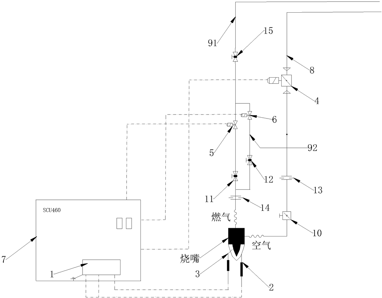
[0035] see figure 1As shown, the present invention relates to a flameless burner control system, including ignition transformer 1, ignition electrode 2, detection electrode 3, air solenoid valve 4, first gas solenoid valve 5, second gas solenoid valve 6, and SCU460 ignition control device 7, the ignition electrode 2 and detection electrode 3 are set at the place where gas and air are mixed in the flameless burner, the air solenoid valve 4 is set on the air pipe 8 communicating with the flameless burner, and the first gas solenoid valve 5 is set On the first gas pipe 91 communicating with the flameless burner, the first gas pipe 91 is connected in parallel with the second gas pipe 92 located at both ends of the first gas solenoid valve 5, and the second gas solenoid valve 6 is arranged on the second gas pipe. 92; wherein the gas control output end of the SCU460 ignition c...


PUM


Abstract

The invention discloses a flameless burner control system, a flameless low-NOx burner and a control method thereof. Through application of a control system taking an SCU460 ignition controller as a core, different actions of a plurality of sets of valves can be automatically controlled according to the flameless combustion and flameless combustion temperature conditions; automatic switching control over different working modes of flameless combustion and flame combustion is achieved, and manual switching is not required, so that the control system is easy to operate, and safe and reliable; meanwhile, the flameless combustion and flame combustion of the burner applying the system can be controlled through the SCU460 ignition controller; during flame combustion, when the furnace temperatureis lower than the set temperature, the burner is ignited by an ignition electrode, and the flame can be detected by a detection electrode; the stable and reliable low-temperature combustion process isensured; in the flameless combustion phase, when the furnace temperature is higher than the set temperature, and the ignition electrode is not ignited; gas and air are injected into a furnace for combustion, and surrounding flue gas can be entrained by high-speed airflow injected into the furnace to take part in combustion; and local high temperature of the flame is reduced greatly, and NOx is reduced quickly.

Description

technical field [0001] The invention relates to the field of burners, in particular to a flameless burner control system and a flameless low NOx burner. Background technique [0002] Flameless combustion, also known as MILD combustion, is a volumetric combustion or diffuse combustion, characterized by low reaction rate, local heat release, uniform heat flow distribution, low combustion peak temperature and low noise, high combustion compared with traditional combustion , the reaction is burned in a large area, even in the entire furnace, so that the flame front is small, and the generation of pollutants such as NOx and CO is drastically reduced. After the technology came out in the early 1990s, it was quickly applied in the iron and steel and metallurgical industries of Germany, Italy, Japan, the United States, Sweden, China and other countries. Because the technology integrates energy saving, emission reduction and environmental protection, this technology is widely used T...

Claims


Application Information

Patent Timeline
Patent Type & Authority Applications(China)
IPC IPC(8): F23D14/02F23D14/62F23N5/20
CPCF23D14/02F23D14/62F23N5/206Y02E20/34
Inventor 王建中吕永超潘映沛颜磊宋付志宋晓敏
Owner FOSHAN KEHAO COMBUSTION EQUIP MFG
Why Eureka
Try Eureka