Electronic splice toy on basis of USB (universal serial bus) interfaces

A USB interface and electronic technology, applied in the field of electronic splicing toys, can solve problems such as splicing methods, splicing sequence requirements, cannot be set, not suitable for young children, etc., and achieve the effect of simplifying the difficulty of not working and free splicing

Inactive Publication Date: 2018-08-14
苏州铁皮人智能科技有限公司
View PDF3 Cites 0 Cited by
  • Summary
  • Abstract
  • Description
  • Claims
  • Application Information

AI Technical Summary

Problems solved by technology

[0003] There are also some toys that can be played by splicing, but they have high requirements for splicing and cannot be spliced ​​at will, so they are not suitable for young children.
Moreover, the current circuit splicing toys have requirements for splicing methods and splicing sequences, and cannot be spliced ​​at will.
The splicing interface between modules needs to be customized. It is not a general interface on the market. Existing circuit splicing toys have a fixed number of module instruction executions and cannot be set.

Method used


Image

  • Electronic splice toy on basis of USB (universal serial bus) interfaces

Examples


Embodiment

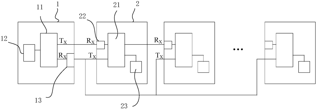
[0021] Such as figure 1 As shown, an electronic splicing toy based on a USB interface includes a main control splicing board 1 and several instruction splicing boards 2, the tail end of the main control splicing board 1 is provided with a main USB socket, and is provided with a receiving data terminal R X and send data terminal T X , each of the first and last ends of the instruction splicing board 2 is respectively provided with a USB plug and a USB socket, and the USB plug is provided with a receiving data terminal R X and send data terminal T X , the USB socket is provided with a sending data terminal T X Each piece of the command splicing board 2 is an independent command splicing board, the USB plug of the rear end of the command splicing board 2 is plugged with the USB socket of the front end of the command splicing board, and the rear end of the command splicing board 2. The receiving data terminal R of the USB plug X The sending data terminal T of the USB socket of...

Embodiment 1

[0027] A small train that can be programmed. The main control board, sound and light, motors and switches are placed in the locomotive. Each small carriage is a command splicing board. The actuators on the command board are printed with forward, left, right and whistle respectively. Wait for the instruction, after the child presses the instruction, after storing it through the secondary memory, splicing the sending data terminal T on the board through the corresponding instruction X Send back to the receiving data terminal R of the main control splicing board X On the top, the splicing board is controlled by the master (the locomotive performs corresponding actions), and the movement sequence of the small train is carried out in accordance with the connection sequence of the small carriages dragged by the rear end.

[0028]In the present invention, the command splicing board is connected with the main control splicing board to control the back-end command splicing board, and t...


PUM


Abstract

The invention relates to an electronic splice toy on the basis of USB (universal serial bus) interfaces. The electronic splice toy comprises a main control splice plate and a plurality of instructionsplice plates. A main USB jack is arranged at the tail end of the main control splice plate, the main control splice plate is provided with a data receiving end RX and a data transmitting end TX, a USB plug and a USB jack are arranged at the head end and the tail end of each instruction splice plate, the USB jacks are provided with data receiving ends RX and data transmitting ends TX, the USB jacks are provided with data transmitting ends TX, the USB plugs of the rear-end instruction splice plates are inserted in the USB jacks of the front-end instruction splice plates, and the USB plugs of the instruction splice plates can be connected with the main USB jack of the main control splice plate. The electronic splice toy has the advantages that the instruction splice plates can be freely combined with one another, and accordingly logical thinking of young children can be exercised in playing procedures; the various instruction splice plates further can be connected with one another in anunordered manner and can be freely spliced, and accordingly the difficulty can be lowered.

Description

technical field [0001] The invention relates to a splicing toy, in particular to an electronic splicing toy based on a USB interface. Background technique [0002] Existing technology just completes various instruction actions on a main circuit, and is operated by remote control or buttons. It is not as deep as the children's understanding of instructions and logical order in the process of splicing by themselves. [0003] There are also some toys that can be played by splicing, but they have high requirements for splicing and cannot be spliced ​​at will, so they are not suitable for young children. Moreover, current circuit splicing toys have requirements for splicing methods and splicing sequences, and cannot be spliced ​​at will. The splicing interface between modules needs to be customized. It is not a general interface on the market. In existing circuit splicing toys, the execution times of module instructions are fixed and cannot be set. [0004] In view of the abov...

Claims


Application Information

Patent Timeline
IPC IPC(8): A63H33/04A63H30/02
CPCA63H33/042A63H30/02
Inventor 刘海兵景日东
Owner 苏州铁皮人智能科技有限公司
Why Eureka
Try Eureka