Multifunctional fixture for bathtub limiting

A multi-functional, bathtub technology, applied in manufacturing tools, workpiece clamping devices, material gluing, etc., can solve the problems of inapplicable fixtures, low production efficiency, inconvenient positioning operations, etc., to improve convenience, save costs, improve The effect of connection firmness

Inactive Publication Date: 2018-08-14
AIFEILING SANITARY WARES TECH GRP CO LTD
View PDF5 Cites 1 Cited by
  • Summary
  • Abstract
  • Description
  • Claims
  • Application Information

AI Technical Summary

Problems solved by technology

Currently, one pair of fixtures is suitable for a bathtub 1 of one size, and one pair of fixtures cannot be applied to bathtubs 1 of other sizes, resulting in a large number of fixtures, inconvenient positioning operations, and low production efficiency.

Method used


Image

  • Multifunctional fixture for bathtub limiting
  • Multifunctional fixture for bathtub limiting
  • Multifunctional fixture for bathtub limiting

Examples


Embodiment 1

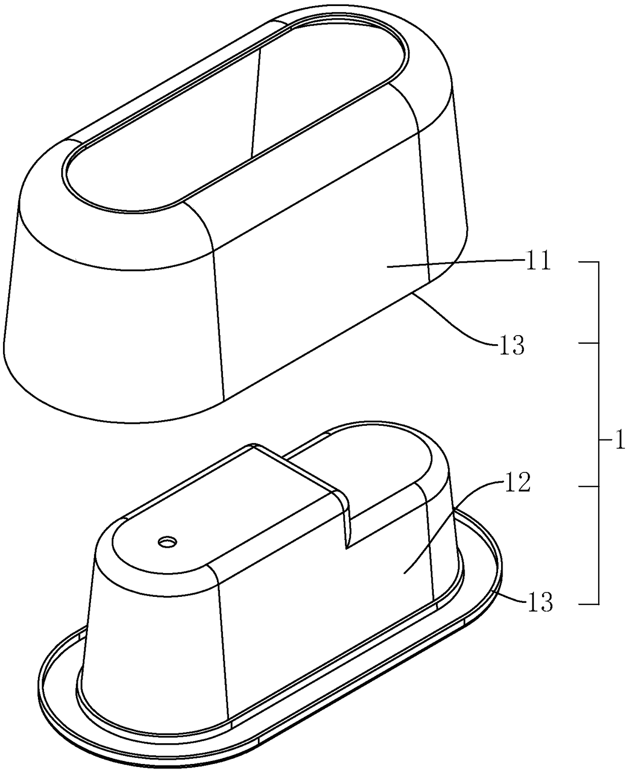
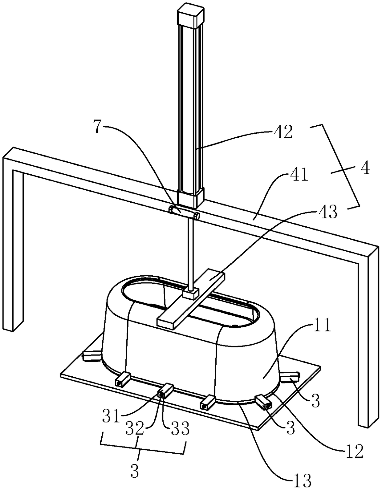
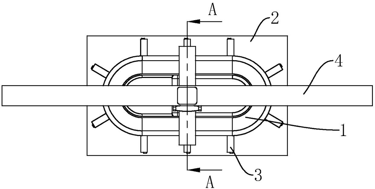
[0029] A multifunctional fixture for bathtub limit, such as figure 2 As shown, the bottom plate 2 made of ferromagnetic material is included. The explanation of ferromagnetic material is: a material that is easily magnetized, such as iron, cobalt, nickel material, etc. A number of magnetic limit seats 3 are provided on the bottom plate 2. The magnetic limit seat 3 includes a housing 31 with a limit surface, a magnet 32 ​​and a control handle 33 for controlling the attraction direction of the magnet 32. The control handle 33 and the magnet 32 ​​are fixedly connected, and the magnet 32 ​​is rotatably connected in the housing 31. The operation of the magnetic limit seat 3 is: rotate the magnet 32 ​​by the control handle 33, the magnetic pole of the magnet 32 ​​is facing the base plate 2, and the housing 31 is adsorbed on the base plate 2, and the magnet 32 ​​is rotated by the control handle 33, and the magnetic pole of the magnet 32 ​​is The bottom plate 2 is not right, and the ...

Embodiment 2

[0035] A multifunctional fixture for bathtub limit, such as Figure 5 with Image 6 As shown, the difference from Embodiment 1 is that the bottom of the bottom plate 2 is provided with a roller 5 and a lifting seat 6. There are at least four rollers 5 and are located at the corners of the bottom plate 2, and the lifting seat 6 is at least four and are located at the corners of the bottom plate 2. The lifting seat 6 includes a rubber seat 61, a screw rod 62 connected to the rubber seat 61, and the screw rod 62 and the bottom plate 2 are screwed. The upper end of the screw rod 62 is provided with a handle, and the handle can be held by the operator to rotate the screw rod 62. The rubber seat 61 is in contact with the ground, which has a certain degree of shock absorption and buffering effect. In addition, the screw 62 and the bottom plate 2 are threaded, so that the floor can be raised while the roller 5 is also raised, so that the roller 5 is separated from the ground.

[0036] ...


PUM


Abstract

The invention discloses a multifunctional fixture for bathtub limiting. The multifunctional fixture has the advantages that the operation convenience degree is improved, the production efficiency is improved, income increasing and expenditure reducing in cost are achieved, efficient utilization of resources is achieved, and cleaner production is achieved. According to the key points of the technical scheme, the multifunctional fixture comprises a bottom plate made of ferromagnetic materials, the bottom plate is provided with a plurality of magnetic limiting seats, and each magnetic limiting seat comprises a shell with a limiting face, a magnet and a control handle used for controlling the attraction direction of the magnet; the control handles are fixedly connected with the magnets, the magnets are rotatably connected into the shells, and the upper portion of the bottom plate is further provided with a downwards-pressing mechanism; and the downwards-pressing mechanism comprises a framebody fixed to the ground, an air cylinder fixed to the frame body and located above a bathtub, and a pressing plate connected to the air cylinder and driven by the air cylinder, and the pressing plate is used for abutting against and pressing the bathtub.

Description

Technical field [0001] The invention relates to the technical field of bathtub production, in particular to a multifunctional clamp used for bathtub positioning. Background technique [0002] Such as figure 1 with figure 2 Shown is an intermediate link in the current production process of bathtub 1. The structure of bathtub 1 includes a segmented first cylinder block 11 and a second cylinder block 12. The first cylinder block 11 and the second cylinder block 12 have the same contour , And this contour needs to be connected to each other and fixed by glue bonding. The contours of the first cylinder 11 and the second cylinder 12 are ring-shaped, and the cross-sectional widths are equal, and the relative positions of the two need to be kept stationary for a period of time after the docking , So that the glue coated on the contour can be cured, so that the first cylinder 11 and the second cylinder 12 are connected as a whole. For the quality and service life of the cylinder, the st...

Claims


Application Information

Patent Timeline
Patent Type & Authority Applications(China)
IPC IPC(8): B25B11/00F16B11/00
CPCB25B11/00B25B11/002F16B11/006
Inventor 林美丽管仙福叶国勇林榆彬
Owner AIFEILING SANITARY WARES TECH GRP CO LTD
Why Eureka
Try Eureka