Visual illusion speed reduction marking lines for curved road section and design method of visual illusion speed reduction marking lines

A technology of deceleration marking and design method, applied in road signs, roads, roads, etc., can solve the problems of less research, limited deceleration effect, and no clearly specified value standard in the specification, so as to improve driving safety, improve driving mood, Reduce the effect of misuse

Active Publication Date: 2018-08-14
CHONGQING JIAOTONG UNIVERSITY
View PDF7 Cites 1 Cited by
  • Summary
  • Abstract
  • Description
  • Claims
  • Application Information

AI Technical Summary

Problems solved by technology

However, there are few studies on the settings of parameters such as the lateral width of deceleration markings, the angle between deceleration markings and lane lines, the width of deceleration markings, and the distance between two adjacent deceleration markings. Some specifications do not clearly stipulate the value standard, and most of the existing research is based on "Technical Standards for Highway Engineering" (JTG B01-2014), "Specifications for the Setting of Highway Traffic Signs and Markings" (JTG D82-2009), "Road "Traffic Signs and Markings" (GB 5768-1999), "Code for Setting Urban Road Traffic Signs and Markings" (GB 51038-2015) and other specifications, the width of the driving lane and the design of the outer dimensions of the vehicle are specified, so as to determine the individual deceleration The horizontal width of the marking line, this setting is relatively random, and its deceleration effect is limited, and in the existing research, it is mainly based on the straight section of the highway, and there is no research on the optical illusion marking of the curved section of the highway

Method used


Image

  • Visual illusion speed reduction marking lines for curved road section and design method of visual illusion speed reduction marking lines
  • Visual illusion speed reduction marking lines for curved road section and design method of visual illusion speed reduction marking lines
  • Visual illusion speed reduction marking lines for curved road section and design method of visual illusion speed reduction marking lines

Examples


Embodiment Construction

[0019] The present invention will be further described below in conjunction with specific embodiment:

[0020] In this embodiment, with the driving direction as the front, when turning left, the inner finger is on the left hand side, and the outer finger is on the right hand side; when turning right, the inner finger is on the right hand side, and the outer finger is on the left hand side. side. The radius of the curved road section refers to the radius of the center line of the lane, and the width of the lane is 3.5m.

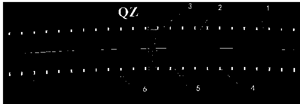
[0021] see figure 1 : Design method of visual illusion deceleration markings on curved highway section, the radius of the curved highway section is 125m ~ 1000m, the design method includes the following steps:

[0022] S1: Set the auxiliary center line:

[0023] Make an arc with a radius of 400~600m as the auxiliary center line 1, so that the curved center point (QZ) of the auxiliary center line 1 intersects with the road center line curved point (QZ) of th...


PUM


Abstract

The invention discloses a design method of visual illusion speed reduction marking lines for a curved road section. The radius of the curved road section is 125-1000m. the method includes the steps ofS1, setting an auxiliary center line, to be more specific, setting an arc-shaped line with the radius being 400-600m to serve as the auxiliary center line; S2, setting an inner-side auxiliary line and an outer-side auxiliary line, to be more specific, shifting the auxiliary center line in S1 towards two sides to form the inner-side auxiliary line and the outer-side auxiliary line; S3, drawing thespeed reduction marking lines, to be more specific, drawing the speed reduction marking lines in one-to-one correspondence between an inner-side lane line and the inner-side auxiliary line and between an outer-side lane line and the outer-side auxiliary line. The design method has the advantages that the speed reduction marking lines are drawn on the road surface according to the visual illusionprinciple of human eyes, a driver can have a curve radius change illusion along with the transverse width change of the speed reduction marking lines, the visual line type of the speed reduction marking lines meets the expectation of the driver, the driving mood of the driver can be improved, misoperation can be reduced, and driving safety can be increased.

Description

technical field [0001] The invention relates to the technical field of road traffic safety, in particular to a false visual deceleration marking on a curved highway section and a design method thereof. Background technique [0002] Optical illusions are the wrong judgments and perceptions based on empiricism or improper reference when people or animals observe objects, directly inducing people's behavior. Optical illusion deceleration markings are based on the principle of visual characteristics. Through a series of special graphic marks, the driver will have the illusion that his own speed is lower than the actual speed, the lane is gradually narrowing, and there are obstacles on the road or roadside during driving. Reduce the speed of the vehicle, thereby playing the role of ensuring traffic safety. Compared with the mandatory speed limit facilities, optical illusion deceleration markings have the function of actively inducing the driver to slow down, and its driving comf...

Claims


Application Information

Patent Timeline
Patent Type & Authority Applications(China)
IPC IPC(8): E01F9/576
CPCE01F9/576
Inventor 尚婷唐伯明刘唐志张勃何丽红曹雪娟郭鹏白婧荣
Owner CHONGQING JIAOTONG UNIVERSITY
Why Eureka
Try Eureka