Compact double-clutch mechanism and transmission system comprising same

A dual-clutch, clutch technology, applied in the field of transmission system, can solve problems such as difficult assembly

Inactive Publication Date: 2018-08-14
VALEO EMBRAYAGES SAS
View PDF1 Cites 1 Cited by
  • Summary
  • Abstract
  • Description
  • Claims
  • Application Information

AI Technical Summary

Problems solved by technology

In a known manner, prior art double clutch mechanisms are difficult to assemble, especially during the step of inserting the elastic return element into the corresponding balancing chamber, because of the need not to block the low pressure conduit during this step

Method used


Image

  • Compact double-clutch mechanism and transmission system comprising same
  • Compact double-clutch mechanism and transmission system comprising same
  • Compact double-clutch mechanism and transmission system comprising same

Examples


Embodiment Construction

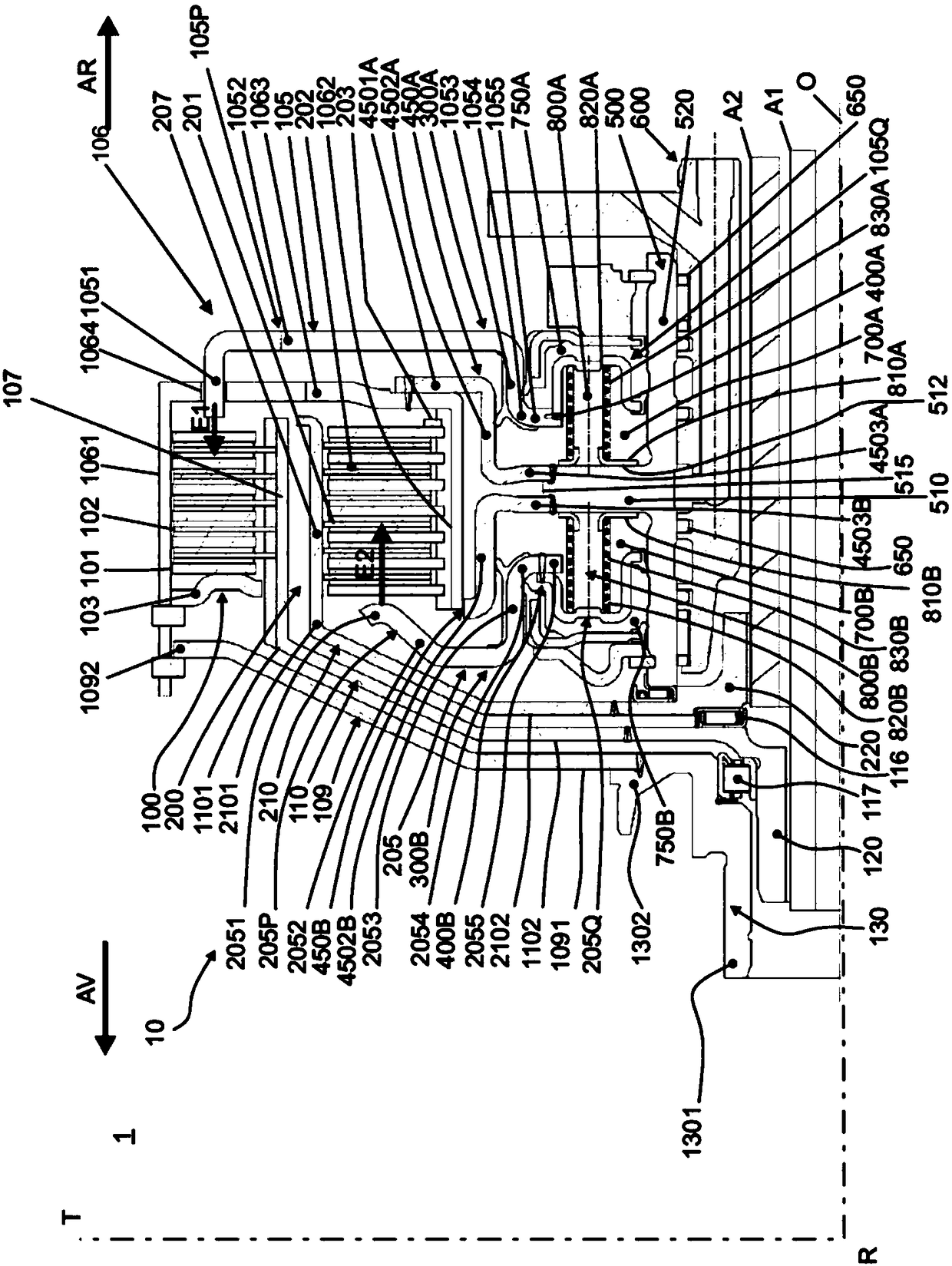
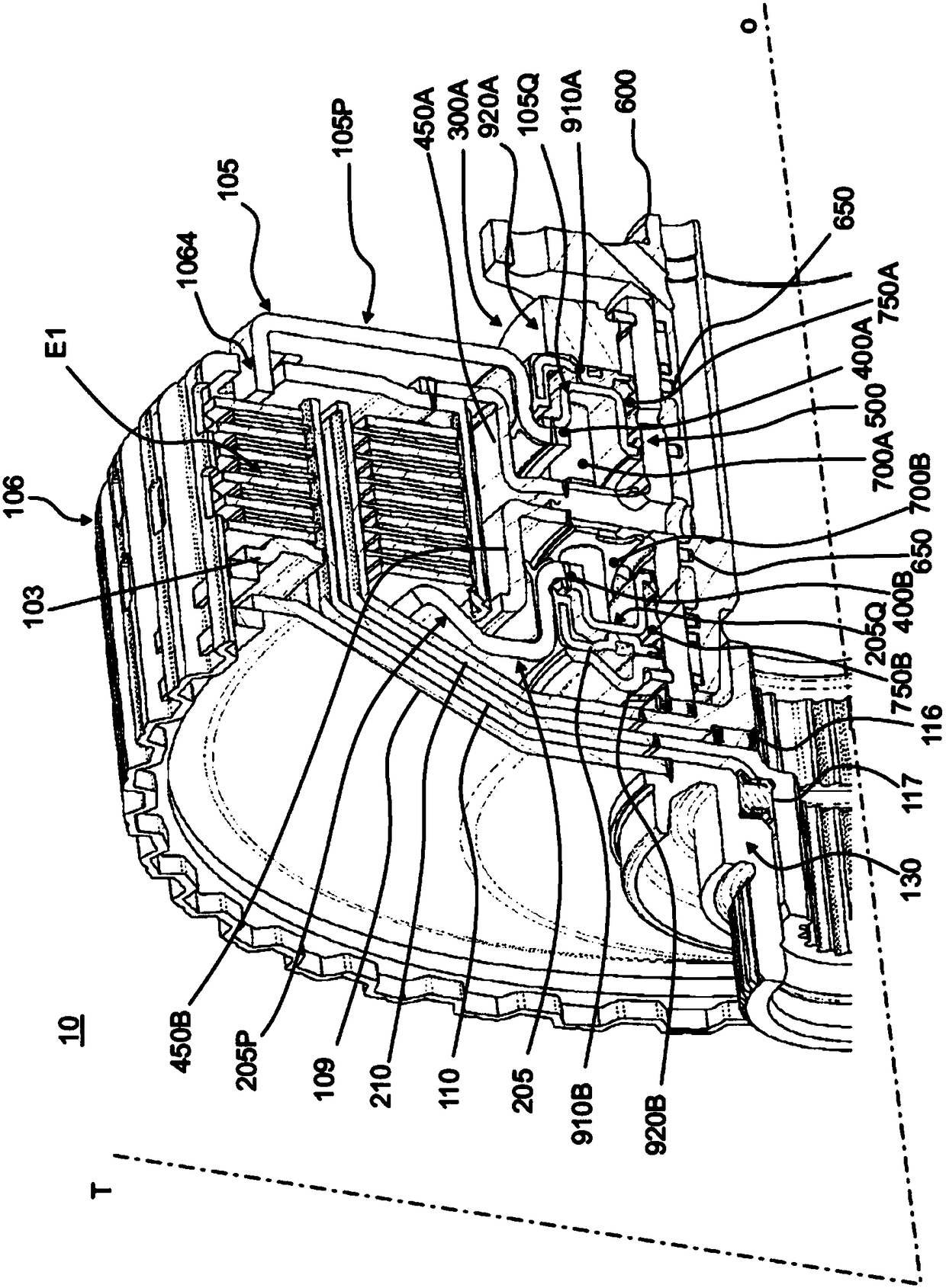
[0071] refer to figure 1 Turning to FIG. 3 , the illustrated embodiment of the dual clutch mechanism 10 according to the first aspect of the invention is preferably of the double wet clutch type and comprises a first clutch 100 and a second clutch 200 . Also preferably, the first clutch 100 is located outside the second clutch 200 in a so-called radial position. Alternatively, the dual clutch mechanism 10 may be in a so-called axial configuration, with the first clutch 100 positioned in front of the second clutch 200 . The dual clutch mechanism 10 is integrated on the transmission chain 1 , and the transmission chain 1 includes a transmission coupled in rotation with the dual clutch mechanism 10 .

[0072] Typically, the dual clutch mechanism 10 is arranged to be capable of rotationally coupling an input shaft (not shown) to the first propeller shaft A1 or alternatively to the second propeller shaft A2 via the first clutch 100 or the second clutch 200, respectively. .

[00...


PUM


Abstract

The invention relates to a double-clutch mechanism (10) in which each actuating system (300A, 300B) comprises a pressure chamber (750A, 750B), an axially movable piston (105, 205), a balancing chamber( 700A, 700B) and an elastic return element (800A, 800B) housed in the balancing chamber and arranged to exert an axial force against said piston. The resilient biasing member (800A, 800B) includes aplurality of apertures (8104) collaborating with a plurality of complementary apertures (5004) located on the central hub (500) to permit fluid communication between a flow conduit fluidic fluid of the central hub and the corresponding balancing chamber and comprises an angular indexing means (8107) collaborating with a complementary angular indexing means (5007) located on the central hub. The invention relates to a transmission system (1) comprising such a double-clutch mechanism (10).

Description

technical field [0001] The invention relates to a compact dual clutch mechanism for the automotive field. The invention also relates to a transmission system incorporating such a dual clutch mechanism. Background technique [0002] The known clutch mechanism comprises a clutch rotating about an axis of rotation, and a force generator arranged to configure the clutch into a so-called disengaged or engaged configuration by means of a movable member called a piston which allows the The force generated at the force generator is transmitted to the clutch. [0003] In a known manner, the actuation system may be formed by a hydraulic pressure generator comprising: (i) a pressure chamber arranged to receive pressurized fluid, (ii) a piston axially movable in the pressure chamber and The outside of the pressure chamber extends radially to engage or disengage the clutch, (iii) a balance chamber, positioned opposite the pressure chamber with respect to the piston, the balance chamber...

Claims


Application Information

Patent Timeline
Patent Type & Authority Applications(China)
IPC IPC(8): F16D25/10F16D25/0638F16D25/12
CPCF16D25/0638F16D25/10F16D25/123F16D25/14F16D13/74F16D2021/0661
Inventor L.科马丹V.科内特H.里博特G.瓦罗奎奥克斯
Owner VALEO EMBRAYAGES SAS
Why Eureka
Try Eureka