
Folding industrial container hoisting device

A technology for hoisting equipment and containers, which is applied in the field of folding industrial container hoisting equipment, and can solve problems such as unsuitability for hoisting industrial containers

Active Publication Date: 2018-08-17
王仁锋
View PDF6 Cites 0 Cited by
  • Summary
  • Abstract
  • Description
  • Claims
  • Application Information

AI Technical Summary

Problems solved by technology

The hoisting system is not suitable for hoisting industrial containers

Method used


Image

  • Folding industrial container hoisting device
  • Folding industrial container hoisting device
  • Folding industrial container hoisting device

Examples


specific Embodiment approach 1

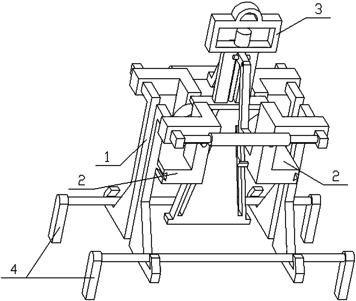
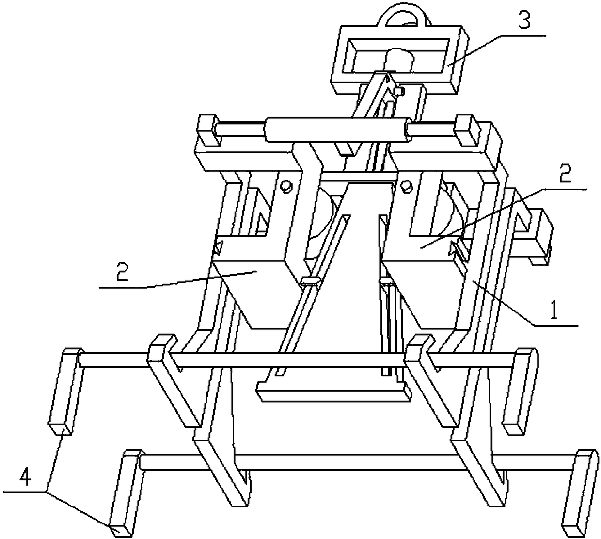
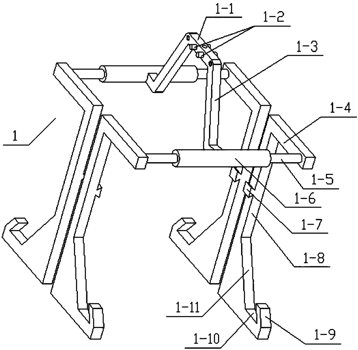
[0023] Combine below Figure 1-8 To illustrate this embodiment, the present invention relates to an industrial appliance, more specifically, a folding industrial container hoisting equipment, which includes a hanger body 1, a side seat body 2 and a hoisting assembly 3, passing rectangular frames 3-5 through When the crane is pulled up, the two L-shaped hangers 1-8 at the left end and the two L-shaped hangers 1-8 at the right end automatically expand outward, and the two L-shaped hangers 1-8 at the front end and the two at the back end The L-shaped hangers 1-8 can also be expanded outward, so that the container can be hoisted by four L-shaped hangers 1-8.

[0024] The hanger body 1 includes a middle crossbar 1-1, a limit cylinder 1-2, an inclined connecting rod 1-3, an upper horizontal sliding rod 1-4, an insert cylinder 1-5, a hollow cylinder 1-6 and L-shaped hanger 1-8, the middle position of the middle cross bar 1-1 is provided with a vertical threaded hole, the middle end of ...


PUM


Abstract

The invention relates to an industrial tool and in particular to a folding industrial container hoisting device. While a rectangular frame is upwards pulled through a hoist, two L-shaped hanging brackets at the left end and two L-shaped hanging brackets at the right end are automatically outwards expanded, and two L-shaped hanging brackets at the front end and two L-shaped hanging brackets at therear end are outwards expanded too, so a container is hoisted by the four L-shaped hanging brackets. A middle position of a middle cross rod is provided with a threaded hole in a vertical direction. The middle end of the middle cross rod is fixedly connected with two limiting columns. The front and rear ends of the middle cross rod are hinged and connected with inclined connecting rods. The lowerends of the two inclined connecting rods are fixedly connected with hollow cylinders. The left and right ends of the two hollow cylinders are slidably connected with inserting columns. An extension spring is welded between the two inserting columns at the front end, and an extension spring is welded between the two inserting columns at the rear end. The two extension springs are positioned in thetwo hollow cylinders. The outer ends of the four inserting columns are fixedly connected with upper cross slide bars.

Description

Technical field [0001] The invention relates to an industrial appliance, more specifically, a folding type industrial container hoisting equipment. Background technique [0002] The application number is CN201420028403.2, a special circular hoisting system for the main reflector of a large antenna, and a special circular hoisting system for the main reflector of a large antenna, including a circular sling, 4-12 hoisting wire rope buckles, and 4-12 Adjustable steel tie rods and 8-24 matching snap rings; the number of hoisting wire rope buckles and adjustable steel tie rods is equal, and the number of snap rings is twice that of adjustable steel tie rods; matching snap rings are used to connect steel tie rods and main reflector lugs And the hoisting wire rope buckle; the annular sling includes a load-bearing ring, the middle of the load-bearing ring is fixedly provided with a boom, the upper end of the boom is opened with a pin hole, and the load-bearing ring is evenly arranged wit...

Claims


Application Information

Patent Timeline
IPC IPC(8): B66C1/42
CPCB66C1/42
Inventor 王仁锋
Owner 王仁锋
Learn More