Transport load spreading device

a technology of transporting load and spreading device, which is applied in the field of agricultural tillage implements, can solve the problems of heavy, costly, and insufficient mounting structure of hydraulic cylinders to the center frame section of tillage implements in such prior art arrangements, and achieve the effect of high load and more evenly distributed

Active Publication Date: 2017-11-09
BLUE LEAF I P
View PDF1 Cites 1 Cited by
  • Summary
  • Abstract
  • Description
  • Claims
  • Application Information

AI Technical Summary

Benefits of technology

[0016]One advantage of the present invention is that the high loads generated by the main hydraulic lift cylinders are more evenly spread through the main frame of the center frame section of the agricultural tillage implement by way of the at least two connecting load members per lug. Another advantage is that the load is transmitted directly to the longitudinal frame members which react in compression, rather than to cross frame members reacting in bending. Still another advantage is that the h

Problems solved by technology

However, in order to support the weight of the entire tillage implement and its wings, the mounting structures connecting the hydraulic

Method used


Image

  • Transport load spreading device
  • Transport load spreading device
  • Transport load spreading device

Examples


Embodiment Construction

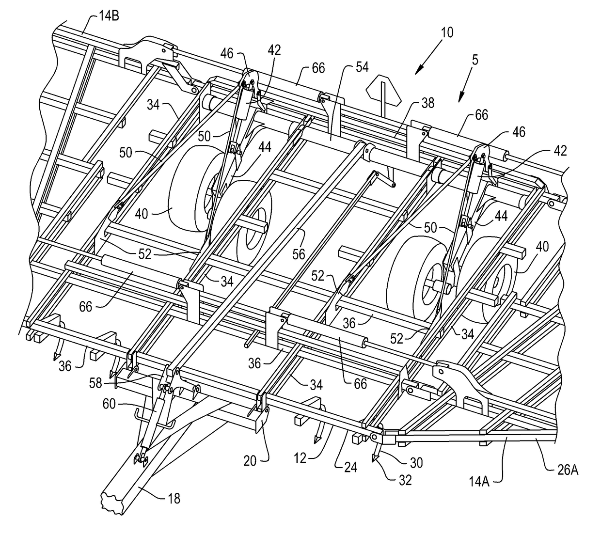
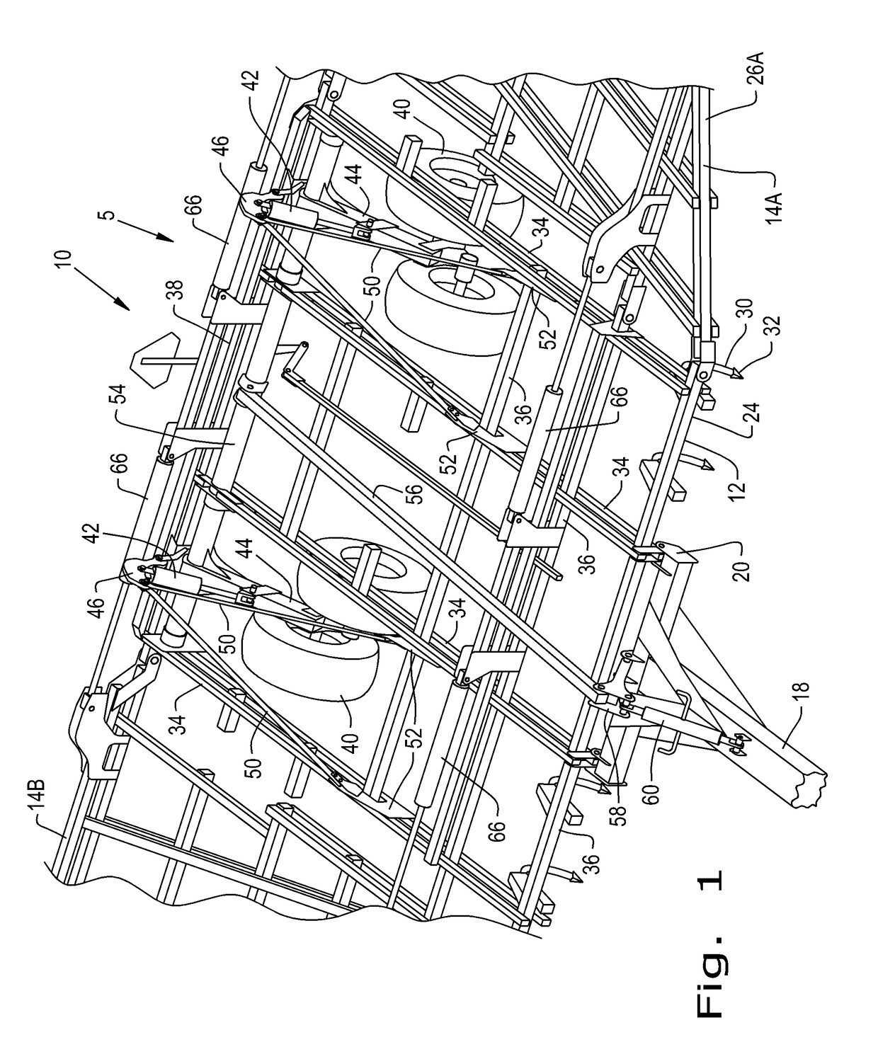
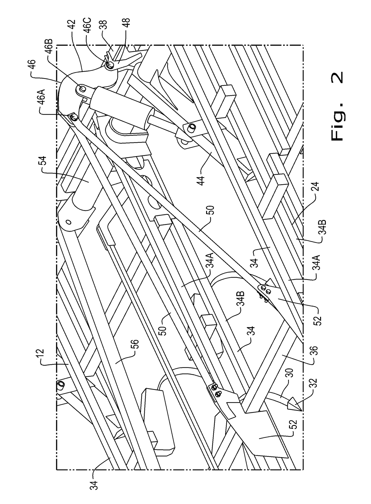
[0026]Referring now to the drawings, and more particularly to FIGS. 1-5, there is shown an agricultural tillage implement 5 according to an embodiment of the present invention, in the form of a field cultivator 10 for tilling and finishing soil prior to seeding. The field cultivator 10 is configured as a multi-section field cultivator, and includes a center frame section 12, left inner wing section 14A, right inner wing section 14B, left outer wing section 16A (not shown), and right outer wing section 16B (not shown). Center frame section 12 is the center section that is directly towed by a traction unit, such as an agricultural tractor (not shown), in a travel direction 22. Center frame section 12 carries main shank frame 24 for tilling the soil, and is connected to pull hitch 18, which extends forward from main shank frame 24 of center frame section 12 in travel direction 22. Pull hitch 18 may be connected to the center frame section 12 by way of a pull hitch hinge 20. Main shank ...


PUM


Abstract

An agricultural or industrial implement has a main frame including longitudinal and cross frame members. Rear main lift wheels are connected to rear lift wheel arms that are pivotally connected to the main frame and can be raised and lowered using a hydraulic lift cylinder. Each hydraulic lift cylinder is connected to a center pivot of a lug. The lug has a lower connection point connected to a lug anchor, which is connected to a rear cross frame member. The lug also has an upper connection point connected to two load members. One of the load members extends diagonally forward from the upper connection point and connects to one of the longitudinal frame members located to the left of the lug. Another of the load members extends diagonally forward from the upper connection point and connects to one of the longitudinal frame members located to the right of the lug.

Description

BACKGROUND OF THE INVENTION1. Field of the Invention[0001]The present invention relates to agricultural implements, and, more particularly, to lift mechanisms for agricultural tillage implements.2. Description of the Related Art[0002]Farmers utilize a wide variety of tillage implements to prepare soil for planting. Some such implements include two or more sections coupled together to perform multiple functions as they are pulled through fields by a tractor. For example, a field cultivator is capable of simultaneously tilling soil and leveling the tilled soil in preparation for planting. A field cultivator has a frame that carries a number of cultivator shanks with shovels at their lower ends for tilling the soil. The field cultivator converts compacted soil into a level seedbed with a consistent depth for providing excellent conditions for planting of a crop. Grass or residual crop material disposed on top of the soil is also worked into the seedbed so that it does not interfere wit...

Claims


Application Information

Patent Timeline
IPC IPC(8): A01B63/22A01B73/04A01B23/04
CPCA01B63/22A01B23/04A01B73/044A01B19/02
Inventor SUDBRINK, MATTHEW R.KNOBLOCH, DEAN A.
Owner BLUE LEAF I P
Why Eureka
Try Eureka