a buckle mechanism

A gusset and gusset technology, applied in the direction of connecting components, mechanical equipment, metal processing equipment, etc., can solve the problems of reduced efficiency and time required, and achieve the effect of small movement range and improved practicability

Active Publication Date: 2020-02-07
福建省鑫锐机械设备有限公司
View PDF5 Cites 0 Cited by
  • Summary
  • Abstract
  • Description
  • Claims
  • Application Information

AI Technical Summary

Problems solved by technology

[0003] However, in the production process, there is also a need for a pushing device for pushing the fixed plate to move. The fixed plate needs to be moved before and after the crimping function. As in the prior art, two power sources are required to complete the pushing of the fixed plate and the lowering of the fixed plate respectively. The action of the crimping plate takes time when switching between two working steps, resulting in a decrease in efficiency, which needs to be improved

Method used


Image

  • a buckle mechanism
  • a buckle mechanism
  • a buckle mechanism

Examples


Embodiment Construction

[0029] The present invention will be described in further detail below in conjunction with the accompanying drawings.

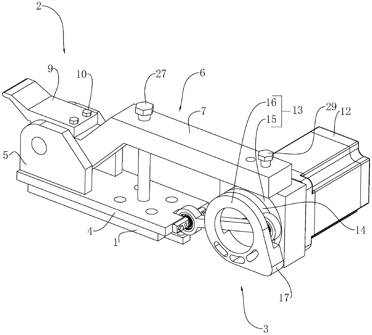
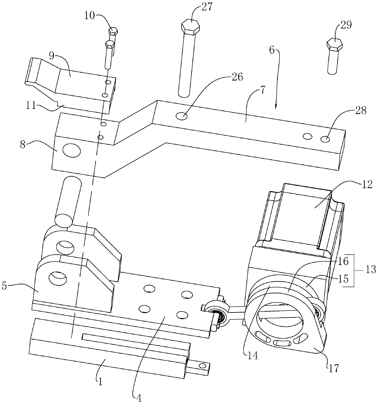
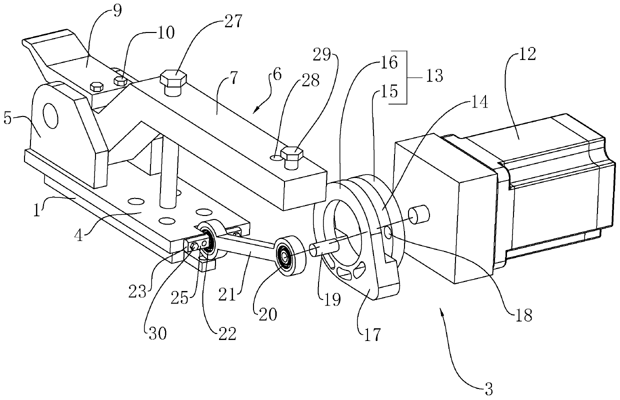
[0030] The embodiment discloses a push button mechanism, such as figure 1 As shown, it includes a bottom plate 1 fixed on the workbench, on which a crimping assembly 2 is slidably installed, and a drive assembly 3 for driving the crimping assembly 2 to move and carry out a crimping action is provided on one side of the bottom plate 1 .

[0031] like figure 1 and figure 2 As shown, the crimping assembly 2 includes a movable plate 4 slidably arranged on the bottom plate 1, and two symmetrically arranged fixed pieces 5 are integrally formed on the movable plate 4, and a buckle plate 6 is hinged between the two fixed pieces 5, and the buckle plate 6 and the hinge of the fixed piece 5 to the end close to the driving assembly 3 is the driving end 7, the hinge of the pinch plate 6 and the fixed piece 5 to the end far away from the driving assembly 3 is the crimpi...


PUM


Abstract

The invention discloses a pushing and buckling mechanism, and relates to radiator installing equipment. According to the technical scheme, the pushing and buckling mechanism comprises a bottom plate,wherein a moving plate and a buckling plate hinged to the moving plate are arranged on the bottom plate in a sliding mode, a driving end is arranged at the hinged position of the buckling plate and the moving plate to one end of the buckling plate, a buckling end is arranged at the hinged position of the buckling plate and the moving plate to the other end of the buckling plate, a rotating part isarranged below the driving end, a driving device used for driving the rotating part to rotate is arranged on one side of the driving end, a pushing rod is arranged between the rotating part and the moving plate, one end of the pushing rod is rotationally connected to the eccentric position of the rotating part, the other end of the pushing rod is rotationally connected to the moving plate, the rotating part is provided with a protruding end which rotates along with the rotating part and forms a pushing effect with the bottom end of the driving end, the protruding end and the driving end are in contact with each other, and the pushing rod pushes the moving plate to move back to the direction of one side of the rotating part. The pushing and buckling mechanism has the effect of improving the working efficiency.

Description

technical field [0001] This invention relates to radiator mounting equipment, and more particularly it relates to a push button mechanism. Background technique [0002] In the prior art, a Chinese patent document with the authorized announcement number CN205437700U discloses a car radiator installation device, which includes a mounting frame, a rotating cylinder and a pressing mechanism. The pressing mechanism includes a fixed plate and a hinged joint with the fixed plate. Buckle plate, the output end of the rotating cylinder is provided with a rotating plate, and the rotating plate is provided with a push block to push the pinch plate to rotate. When the rotating motor is working, the push block on the rotating plate rotates with the rotating plate, thereby pushing the pinch plate to realize buckling Function. [0003] However, in the production process, there is also a need for a pushing device for pushing the fixed plate to move. The fixed plate needs to be moved before ...

Claims


Application Information

Patent Timeline
Patent Type & Authority Patents(China)
IPC IPC(8): B23P19/02F16B4/00
CPCF16B4/004
Inventor 葛建明黄安英
Owner 福建省鑫锐机械设备有限公司
Why Eureka
Try Eureka