
Touch Sensing Electrode Structure

A technology of touch sensing electrodes and sensing electrodes, which is applied in the direction of electrical digital data processing, instruments, calculations, etc., can solve the problems of easy mutual interference of electrodes, short service life, inaccurate control, etc., and achieve the protection of sensing electrodes and long service life Longer, more precise effects

Active Publication Date: 2021-03-30
SHENZHEN ZHILING WEIYE TECH
View PDF2 Cites 0 Cited by
  • Summary
  • Abstract
  • Description
  • Claims
  • Application Information

AI Technical Summary

Problems solved by technology

[0003] 1. The touch sensing electrode structure in the existing mobile phone is easy to interfere with each other when touching the adjacent electrodes after long-term use, resulting in inaccurate control;
[0004] 2. The substrate and electrodes in the touch sensing electrode structure in the mobile phone are often severely worn due to long-term contact during actual use, and the service life is short;
[0005] 3. Different electrode sensing pads in the touch sensing electrode structure of the mobile phone may sometimes shift in position when they are dropped or otherwise affect the use

Method used


Image

  • Touch Sensing Electrode Structure
  • Touch Sensing Electrode Structure
  • Touch Sensing Electrode Structure

Examples


Embodiment Construction

[0023] The following will clearly and completely describe the technical solutions in the embodiments of the present invention with reference to the accompanying drawings in the embodiments of the present invention. Obviously, the described embodiments are only some, not all, embodiments of the present invention. Based on the embodiments of the present invention, all other embodiments obtained by persons of ordinary skill in the art without making creative efforts belong to the protection scope of the present invention.

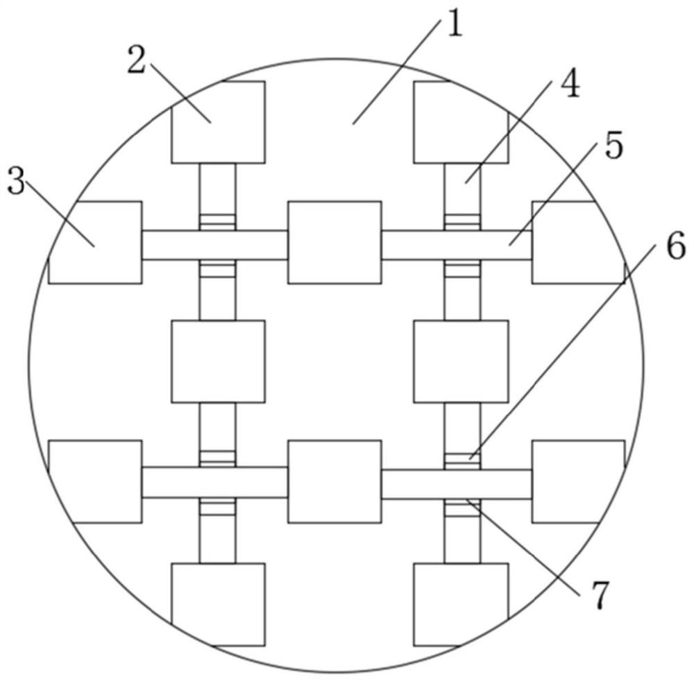
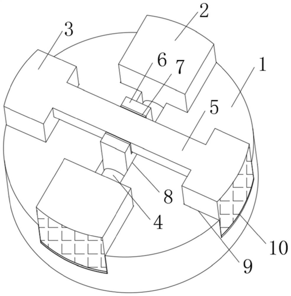
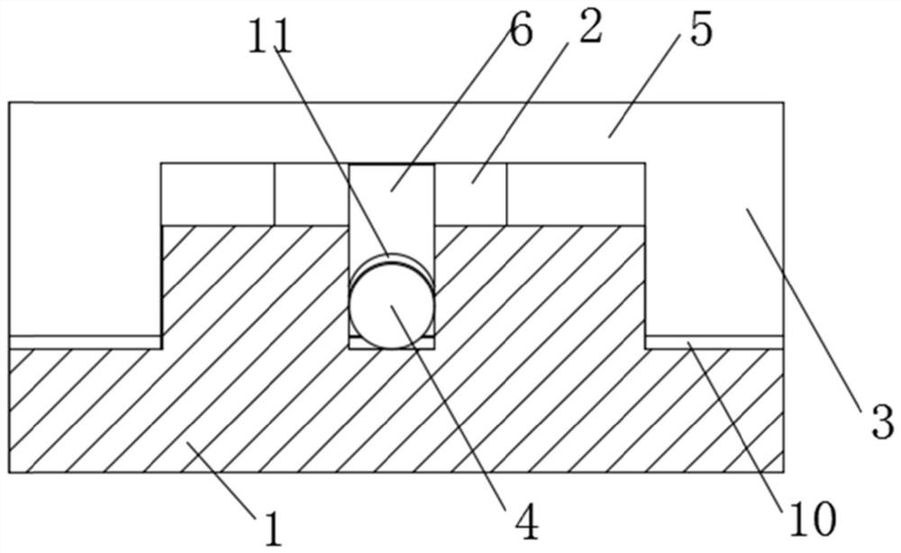
[0024] see Figure 1-4 The present invention provides a technical solution: a touch sensing electrode structure, including a substrate 1, a first sensing electrode 2, a second sensing electrode 3, a wire 4 and a bridge 5, and the surface of the substrate 1 is embedded with the first sensing electrode 2 and The second induction electrode 3, the first induction electrode 2 and the second induction electrode 3 are provided with a plurality of equal distances and ...


PUM


Abstract

The invention discloses a touch induction electrode structure. The structure comprises a substrate, first induction electrodes, second induction electrodes, a lead wire and an electric bridge, whereinthe surface of the substrate is inlaid with the first induction electrodes and the second induction electrodes; the adjacent first induction electrodes are connected through the lead wire; the adjacent second induction electrodes are connected through the electric bridge; the first induction electrodes and the second induction electrodes are clamped in fixing slots of the upper surface of the substrate; the first induction electrodes and the second induction electrodes are difficultly disturbed mutually, so that the control precision is improved; protective boards are laminated on the lower surfaces of the first induction electrodes and the second induction electrodes; the protective boards have the effects of protecting the induction electrodes, so that the wear between the substrate andthe induction electrodes is reduced and the service life is relatively long; and the lower ends of the first induction electrodes and the second induction electrodes are clamped in the fixing slots,so that the induction electrodes are difficultly shifted due to fall damage or other situations, the positions are relatively fixed, and the use is not influenced.

Description

technical field [0001] The invention relates to the technical field of touch sensing electrode structures, in particular to the structure of touch sensing electrodes. Background technique [0002] The touch sensing electrode is a structure composed of a transparent electrode and a touch sensing panel. The principle of induction uses voltage to act on the four corners of the screen sensing area to form a fixed electric field. When the finger touches the screen, the electric field can cause a current to be measured by the controller, depending on the ratio of the current to the four corners. Calculate the contact position to achieve the purpose of touch sensing, but it still has the following disadvantages in actual use: [0003] 1. The touch sensing electrode structure in the existing mobile phone is easy to interfere with each other when touching the adjacent electrodes after long-term use, resulting in inaccurate control; [0004] 2. The substrate and electrodes in the to...

Claims


Application Information

Patent Timeline
Patent Type & Authority Patents(China)
IPC IPC(8): G06F3/041
CPCG06F3/041
Inventor 苏伟王雷王海峰高荣亮
Owner SHENZHEN ZHILING WEIYE TECH
Learn More