A Large-Scale Multiple-Input-Output Wireless Channel Emulator
A wireless channel, input and output technology, applied in the field of electronic information, can solve the problem of a small number of channels, and achieve the effect of improving work efficiency and simplifying complexity
- Summary
- Abstract
- Description
- Claims
- Application Information
AI Technical Summary
Problems solved by technology
Method used
Image

Examples
Embodiment 1
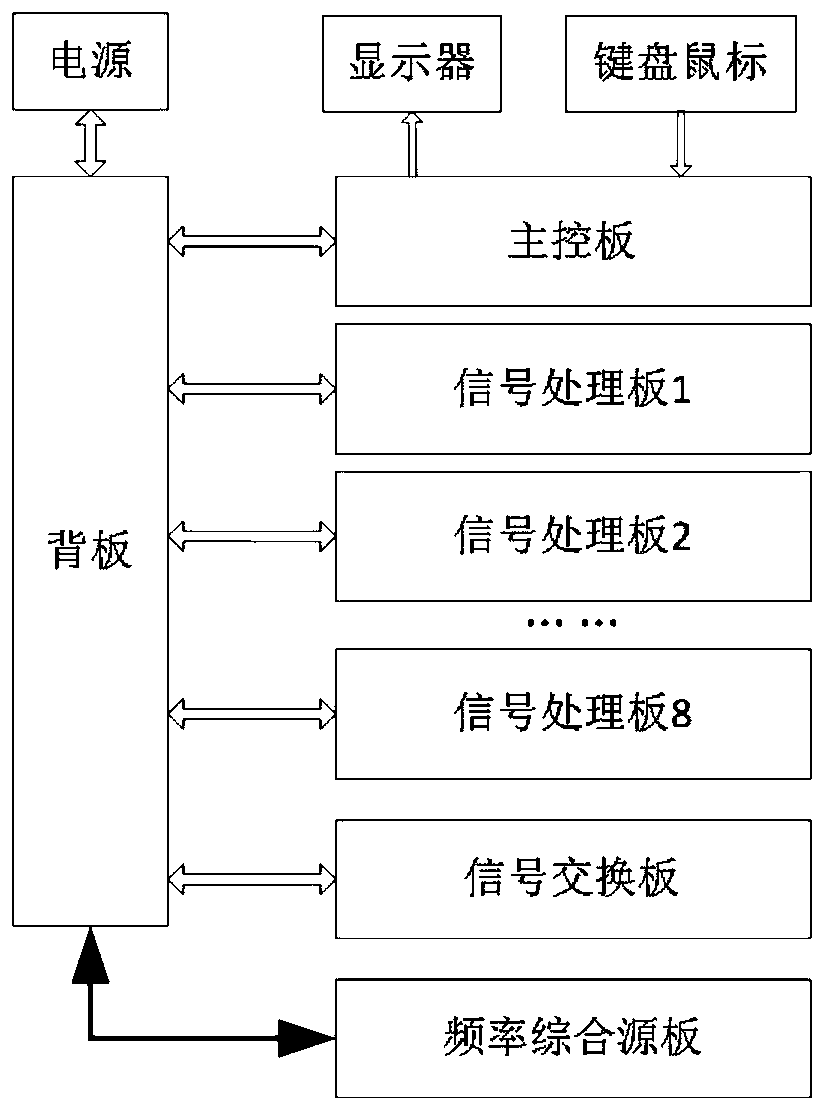
[0019] Such as figure 1 As shown, a large-scale multi-input and output wireless channel emulator is composed of multiple signal processing boards, signal exchange boards, frequency synthesis source boards, main control boards, backplanes, power supplies, external monitors, keyboards and mice, wherein the signal The specific application number of processing boards can be selected from 1 to 8 in actual application.
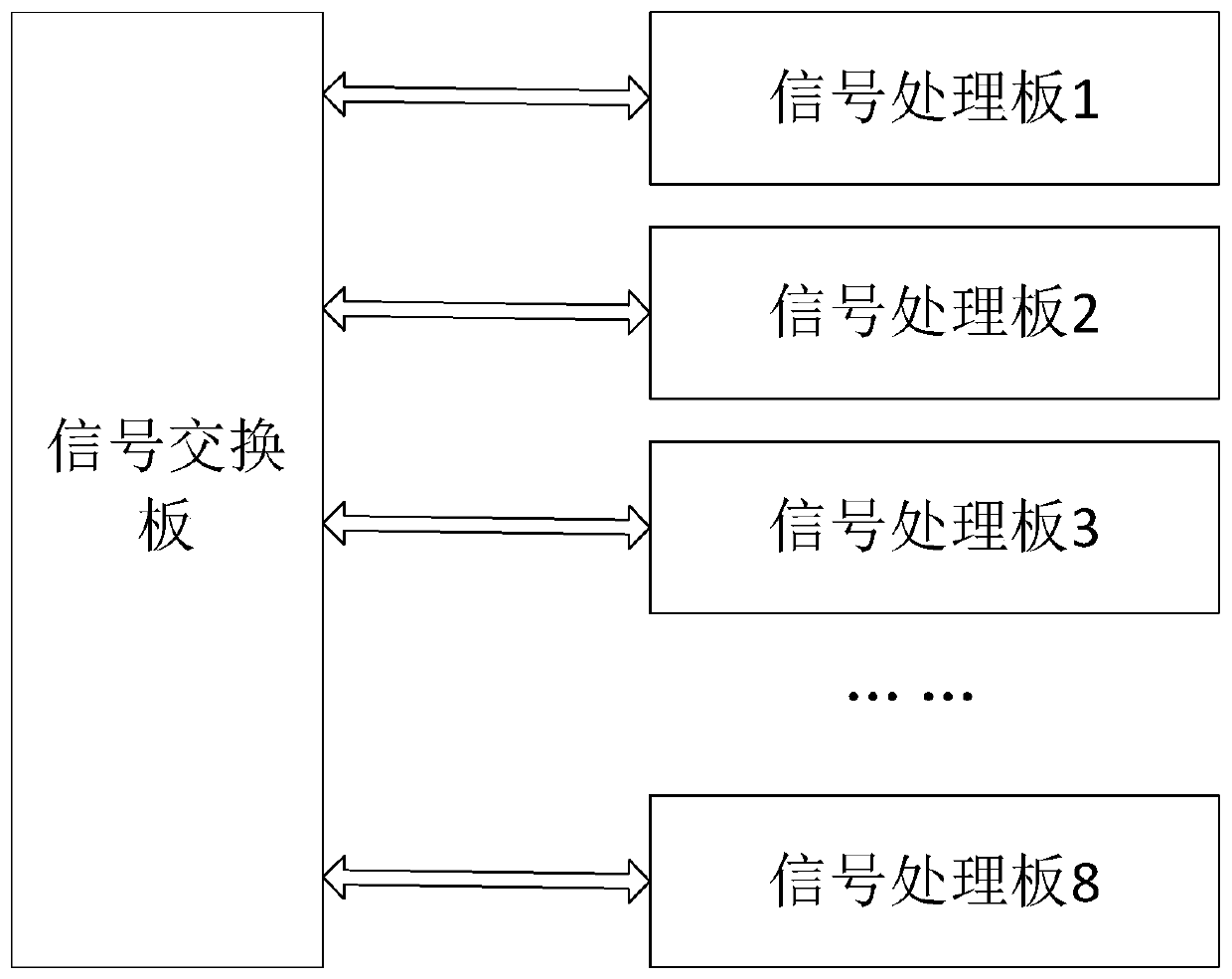
[0020] The signal processing board completes the processing of input signals, the simulation of input signals and the output of signals. The frequency synthesis source board provides local oscillator signals for each signal processing board. The signal exchange board completes the data exchange between multiple signal processing boards. The main control board Run the man-machine interface software, each signal processing board, frequency integrated source board and main control board realize the transmission of control signals through the backplane, the power supply...
Embodiment 2
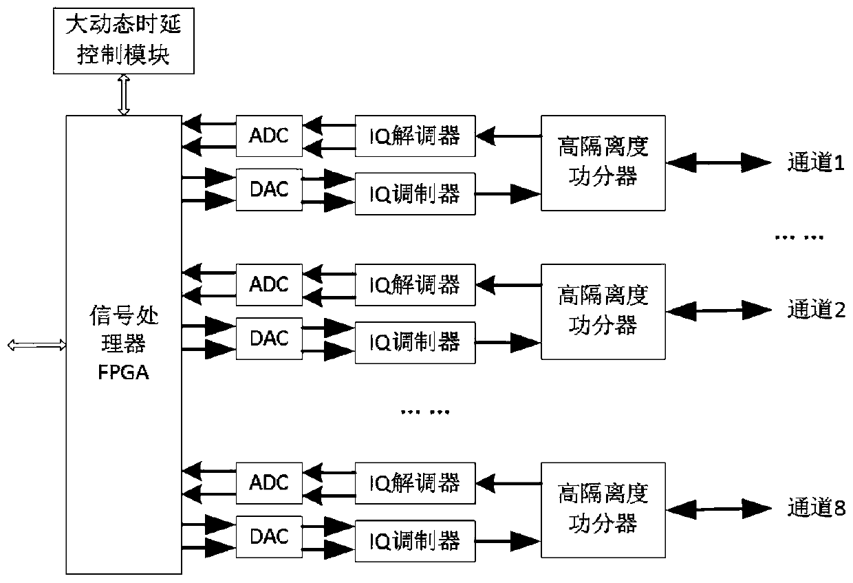
[0022] Such as figure 2 As shown, each signal processing board contains a maximum of 8 input and output channels, and each input and output duplex channel includes 1 high-isolation power divider, 1 IQ demodulator, 1 ADC, 1 DAC, 1 IQ modulator, 1 large dynamic delay control module, 8 input and output duplex channels share 1 signal processor FPGA, and 1-8 channels can be selected for input and output duplex channels in practical applications.
[0023] Through 8 signal processing boards, each signal processing board is configured with 8 channels, realizing the design of 64 channels for a single device. Furthermore, if the number of channels required is less than 64 channels, it is only necessary to reduce the channel hardware configuration of the signal processing board or a certain signal processing board according to the number of channels.
Embodiment 3
[0025] Implementation of automatic phase calibration: such as figure 2 As shown, the signal processing FPGA of a signal processing board generates a continuous wave digital signal and outputs it to the DAC. After being converted by the DAC, two signals of I and Q are formed. After passing through the IQ modulator, an analog signal is formed and output to the high isolation power The signal is input to the IQ demodulator through the high-isolation power divider and demodulated into I and Q two-way signals, which are collected by the ADC and then input to the FPGA, which completes the signal processing project of self-sending and self-receiving. The FPGA calculates the phase error between the sent signal and the received signal, and obtains the phase error of this channel. The FPGA calculates the phase error of all channels in turn, and selects the phase error of the first channel as a reference value, and the phase error of the other channels Compared with the phase error of t...
PUM
 Abstract
Description
Claims
Application Information
 - R&D
- Intellectual Property
- Life Sciences
- Materials
- Tech Scout
- Unparalleled Data Quality
- Higher Quality Content
- 60% Fewer Hallucinations
Browse by: Latest US Patents, China's latest patents, Technical Efficacy Thesaurus, Application Domain, Technology Topic, Popular Technical Reports.
© 2025 PatSnap. All rights reserved.Legal|Privacy policy|Modern Slavery Act Transparency Statement|Sitemap|About US| Contact US: help@patsnap.com