
Self moving device

A self-moving and equipment technology, which can be used in motor vehicles, non-electric variable control, instruments, etc., and can solve the problems of high cost and complicated installation of state detection devices.

Pending Publication Date: 2018-08-21
POSITEC POWER TOOLS (SUZHOU) CO LTD
View PDF3 Cites 6 Cited by
  • Summary
  • Abstract
  • Description
  • Claims
  • Application Information

AI Technical Summary

Problems solved by technology

[0004] Based on this, it is necessary to provide a self-moving device and its state detection method with simple installation and low cost for the problems of complex installation and high cost of existing state detection devices

Method used


Image

  • Self moving device
  • Self moving device
  • Self moving device

Examples


Embodiment Construction

[0061] In order to facilitate the understanding of the present invention, the present invention will be described more fully below with reference to the associated drawings. Preferred embodiments of the invention are shown in the accompanying drawings. However, the present invention can be embodied in many different forms and is not limited to the embodiments described herein. On the contrary, these embodiments are provided to make the understanding of the disclosure of the present invention more thorough and comprehensive.

[0062]In the description of the present invention, it should be noted that the terms "center", "upper", "lower", "left", "right", "vertical", "horizontal", "left", "right", The orientation or positional relationship indicated by "inner", "outer", etc. is based on the orientation or positional relationship shown in the drawings, and is only for the convenience of describing the present invention and simplifying the description, rather than indicating or i...


PUM


Abstract

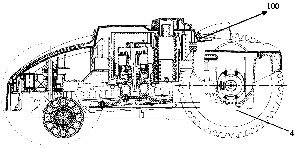
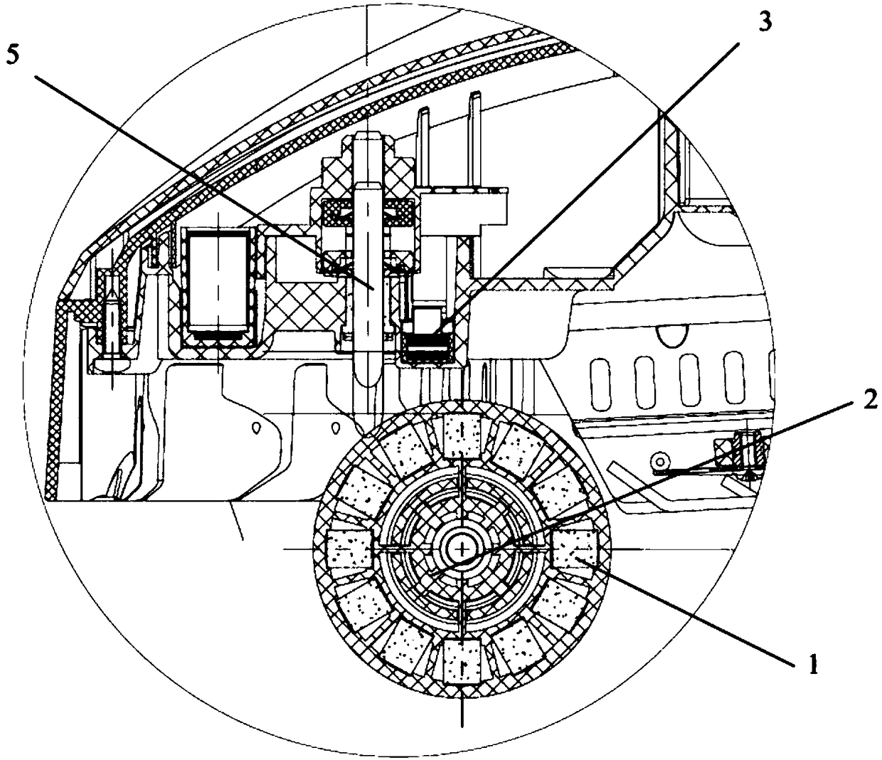
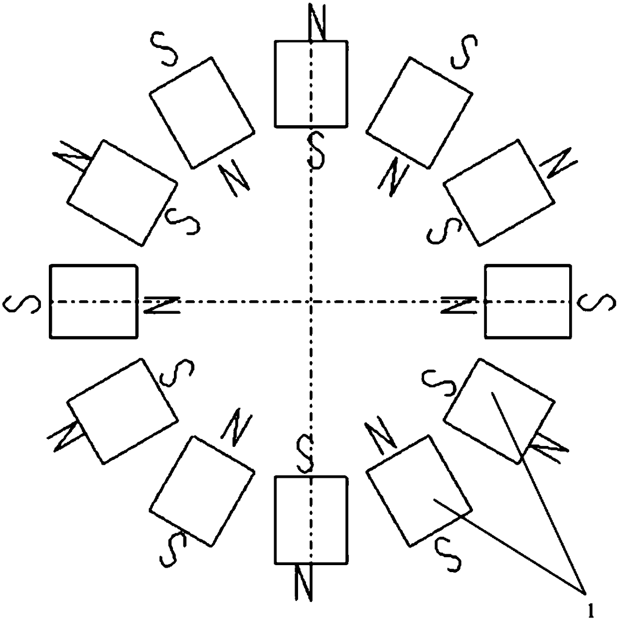
A self moving device comprises a housing, a travelling mechanism supporting and driving the self moving device to travel, a control device used for controlling the self moving device to travel and work and a state detection device, wherein the travelling mechanism comprises a driving wheel and a driven wheel; the state detection device comprises at least two magnetic triggering members, a signal induction device and a detection device; the at least two magnetic triggering members are arranged on the driven wheel and can rotate along with the driven wheel, the neighboring magnetic triggering members are different in polarity of one end on the same side as the driven wheel, the signal induction device is used for inducting magnetic field signals generated by the magnetic triggering members and generating induction signals, and the detection device is used for determining a rotation state of the driven wheel according to the induction signals so as to determine whether the self moving device can travel normally.

Description

technical field [0001] The invention relates to the technical field of walking equipment, in particular to a self-moving equipment. Background technique [0002] With the continuous advancement of science and technology, various mobile devices have gradually entered people's lives, such as vacuum cleaners and automatic lawn mowers. This kind of self-moving equipment has a walking device, a working device and an automatic control device, so that it can walk and perform work automatically within a certain range without being operated by people. [0003] Generally, there are often some obstacles in the working area of ​​the self-moving device, which may affect the work of the self-moving device or even damage the self-moving device. An existing solution is to set a floating part on the base of the self-moving device. When the self-moving device collides with an obstacle, the relative displacement between the floating part and the base occurs, and the relative displacement is d...

Claims


Application Information

Patent Timeline
Patent Type & Authority Applications(China)
IPC IPC(8): G05D1/02
CPCG05D1/0259
Inventor 兰彬财周潇迪高萍杜江连洪奎
Owner POSITEC POWER TOOLS (SUZHOU) CO LTD
Learn More