
Hoisting device and hoisting method for serpentine tube panel

A hoisting device and serpentine tube technology, which is applied in the direction of boiler support/positioning device, transportation and packaging, load hanging components, etc., can solve the problems of serpentine tube deformation, poor rigidity, easy deformation, etc., to prevent deformation, Stable and reliable connection, good quality effect

Active Publication Date: 2019-08-30
CHINA MCC5 GROUP CORP
View PDF7 Cites 0 Cited by
  • Summary
  • Abstract
  • Description
  • Claims
  • Application Information

AI Technical Summary

Problems solved by technology

[0002] At present, the superheater of the biomass furnace often involves the installation of a large number of serpentine tube panels. The serpentine tube panel has the characteristics of large plane size, poor rigidity, and easy deformation. It is inconvenient to use, and the connection stability with the whole serpentine tube screen is not good, and the serpentine tube is often deformed during the hoisting process, causing serious damage to the quality of the serpentine tube, which leads to the failure of the installation process to proceed smoothly, and cannot guarantee subsequent Usage requirements

Method used


Image

  • Hoisting device and hoisting method for serpentine tube panel
  • Hoisting device and hoisting method for serpentine tube panel
  • Hoisting device and hoisting method for serpentine tube panel

Examples


Embodiment 1

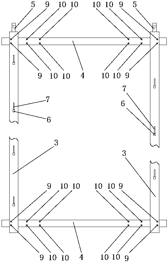
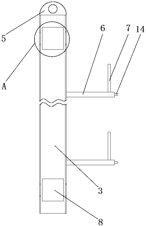
[0026] like figure 1 , 2 As shown in and 8, the hoisting device for the serpentine tube panel, the serpentine tube panel consists of several straight pipes 1 and several elbows 2, including two left and right vertical beams 3 and two upper and lower beams 4, the four are fixedly connected to form a A rectangular frame, two vertical beams 3 with lifting lugs 5 at the top, a number of horizontal support rods 6 are fixedly installed on the two vertical beams 3, the horizontal support rods 6 are covered with rubber sleeves (not shown in the figure), the horizontal support rods 6 is used to contact the outer surface of the straight tube 1 of the serpentine tube screen and form a vertical support. The cross-sectional shape of the horizontal support rod 6 is rectangular, and one of its horizontal planes is used to contact the outer surface of the straight tube 1 of the serpentine tube screen. The horizontal support rods 6 on the two vertical beams 3 form upper and lower staggered fl...

Embodiment 2

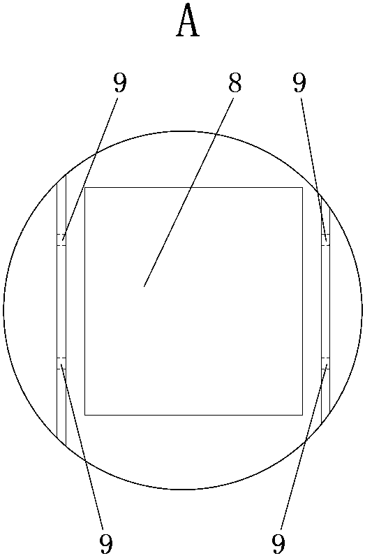
[0028] like Figures 1 to 3 , 6 and 7, on the basis of embodiment 1, the vertical beam 3 and the cross beam 4 are I-beams, and the upper and lower ends of the vertical beam 3 webs are provided with installation through holes 8, and at the vertical beam 3 two ends Two connection holes 9 are provided on the board corresponding to the positions of the installation through holes 8, and at least two groups of matching holes 10 are respectively provided at the left and right ends of the two ends of the beam 4, and three groups of matching holes 10 are specifically set here, namely Three groups of matching holes 10 are respectively provided at the left end and the right end of each end plate, and each group includes two matching holes 10, and there is a distance between adjacent groups of matching holes 10, and the left and right ends of the crossbeam 4 are correspondingly inserted into the two vertical beams 3 at the same time. In the installation through hole 8 at the end, the two ...

Embodiment 3

[0030] like figure 2 , 4 As shown in and 5, on the basis of Embodiment 2, the end of the horizontal support rod 6 is provided with a vertical adjustment through hole 11, and the limit rod 7 is inserted in the adjustment through hole 11, and is matched, and the limit The upper end and the lower end of the rod 7 are respectively provided with a limit hole 12, and the end of the horizontal support rod 6 is provided with an axial step hole 13, and an axial step shaft 14 is installed in the step hole 13, and the step shaft 14 includes an annular step. And the shaft part, the step shaft 14 is covered with a compression spring 15, when the step shaft 14 is installed in the step hole 13, the compression spring 15 can be installed in the step hole 13 first, and then pass through the shaft part, and the shaft parts pass through in turn Over compress the spring 15 and the annular step, and then weld the annular step and the shaft. The two ends of the compression spring 15 are respectiv...


PUM


Abstract

The invention relates to the technical field of mounting of snake-shaped tube panels, and discloses a hoisting device and method of a snake-shaped tube panel. The snake-shaped tube panel comprises a plurality of straight tubes and a plurality of elbows. The device is characterized by comprising a left vertical beam, a right vertical beam, an upper cross beam and a lower cross beam which are fixedly connected to form a rectangular frame; lugs are arranged on the top ends of the two vertical beams; a plurality of horizontal supporting rods are fixedly mounted on the two vertical beams, and the horizontal supporting rods are in contact with the outer surfaces of the straight tubes of the snake-shaped tube panels and realize vertical supporting; limiting rods are mounted at the end parts of the horizontal supporting rods and are in contact with the outer surfaces of the straight tubes of the snake-shaped tube panel and realize horizontal limitation, and the snake-shaped tube panel is prevented from being horizontally separated from the horizontal supporting rods by the horizontal limitation. The device can be stably and reliably connected to the whole snake-shaped tube panel, and the operation is convenient and quick; a large-size snake-shaped tube panel can be smoothly and stably hoisted and carried to a specified position; and the snake-shaped tube panel is kept in high quality and prevented from deformation during being hoisted.

Description

technical field [0001] The invention relates to the technical field of installation of a serpentine tube panel, in particular to a hoisting device for a serpentine tube panel and a hoisting method thereof. Background technique [0002] At present, the superheater of the biomass furnace often involves the installation of a large number of serpentine tube panels. The serpentine tube panels have the characteristics of large plane size, poor rigidity, and easy deformation. It is inconvenient to use, and the connection stability with the whole serpentine tube screen is not good, and the serpentine tube is often deformed during the hoisting process, causing serious damage to the quality of the serpentine tube, resulting in the failure of the installation process to proceed smoothly, and the subsequent Usage requirements. [0003] Therefore, this application proposes a hoisting device and hoisting method for a serpentine tube panel, which can be stably and reliably connected to th...

Claims


Application Information

Patent Timeline
Patent Type & Authority Patents(China)
IPC IPC(8): B66C1/22F22B37/24
Inventor 潘贞君何涌
Owner CHINA MCC5 GROUP CORP
Learn More