Roll-weakening device of crane

A technology of anti-rolling devices and cranes, which is applied in hoisting devices, transportation and packaging, clockwork mechanisms, etc., and can solve problems such as precise positioning and accurate stacking of unfavorable goods, potential safety hazards, damaged ground and heavy objects

Pending Publication Date: 2018-08-24
HENAN ZHONGYUAN HOIST MACHINERY
View PDF0 Cites 0 Cited by
  • Summary
  • Abstract
  • Description
  • Claims
  • Application Information

AI Technical Summary

Problems solved by technology

[0002] A crane is a large-scale handling equipment, mainly used for cargo handling in warehouses, docks, etc.; the main components of the crane include a support frame, a main beam, a running trolley and a hook placed under the running trolley; the goods are hung by hooks Traction, moving to the designated position through the handling of the running trolley; in the process of hoisting and handling, the heavy object will swing back and forth in the plumb plan

Method used


Image

  • Roll-weakening device of crane
  • Roll-weakening device of crane
  • Roll-weakening device of crane

Examples


Example Embodiment

[0016] Example 1

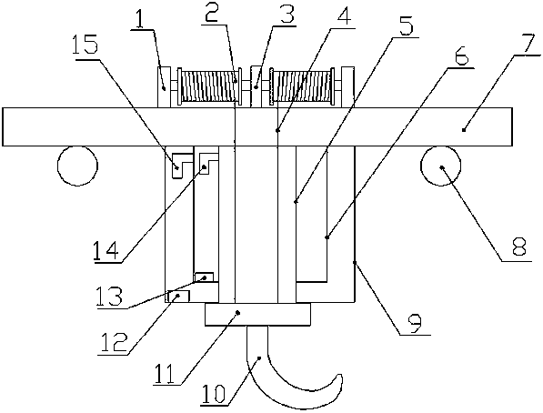
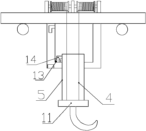
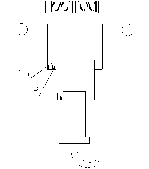
[0017] like Figure 1-4 Shown, a kind of anti-rolling device of crane, it comprises trolley 7, and described trolley 7 is equipped with wheel 8 on both sides of the lower end, and the middle part of the lower end of described trolley 7 is welded with outer cylinder 9, and described outer cylinder 9 is sleeved with a middle cylinder 6, said middle cylinder 6 is sleeved with an inner cylinder 5, said outer cylinder 9 is provided with a groove A12 on the left side of the inner lower end, said middle cylinder 6 has a top left side A protrusion A15 matching with the groove A12 is fixedly connected, a groove B13 is provided on the left side of the inner lower end of the middle cylinder 6, and a groove B13 is fixedly connected on the upper left side of the inner cylinder 5 to match the groove B13. The protrusion B14, the upper end of the outer cylinder 9 and the middle cylinder 6 are provided with through holes, the upper end and lower end of the inner cylinder 5 ...

Example Embodiment

[0019] Example 2

[0020] like Figure 1-4 Shown, a kind of anti-rolling device of crane, it comprises trolley 7, and described trolley 7 is equipped with wheel 8 on both sides of the lower end, and the middle part of the lower end of described trolley 7 is welded with outer cylinder 9, and described outer cylinder 9 is sleeved with a middle cylinder 6, said middle cylinder 6 is sleeved with an inner cylinder 5, said outer cylinder 9 is provided with a groove A12 on the left side of the inner lower end, said middle cylinder 6 has a top left side A protrusion A15 matching with the groove A12 is fixedly connected, a groove B13 is provided on the left side of the inner lower end of the middle cylinder 6, and a groove B13 is fixedly connected on the upper left side of the inner cylinder 5 to match the groove B13. The protrusion B14, the upper end of the outer cylinder 9 and the middle cylinder 6 are provided with through holes, the upper end and lower end of the inner cylinder 5 ...


PUM


Abstract

The invention discloses a roll-weakening device of a crane. The roll-weakening device comprises a trolley, wherein the middle part of the lower end of the trolley is welded with an outer barrel; a middle barrel is connected in the outer barrel in a sleeving mode; an inner barrel is connected in the middle barrel in the sleeving mode; a groove A is formed in the left side of the lower end in the outer barrel; the upper part of the left side surface of the middle barrel is fixedly connected with a bulge A matched with the groove A; a groove B is formed in the left side of the lower end in the middle barrel; the upper part of the left side surface of the inner barrel is fixedly connected with a bulge B matched with the groove B; a motor, a speed reducer and a winding drum mechanism are mounted at the upper end of the trolley; the output shaft of the motor is connected with a high-speed shaft of the speed reducer through a shaft coupler; the winding drum mechanism is composed of winding drums which are symmetrically arranged at the two sides of the speed reducer; the two ends of each winding drum are separately mounted on the trolley through bearing bases; steel wire ropes are mountedon the winding drums; the inner barrel and the lower ends of the steel wire ropes are fixedly connected with a fixed plate; and the lower end of the fixed plate is fixedly connected with a hanger. Theroll-weakening device has the advantages of being simple and convenient to operate, capable of reducing hanger swing, and being good in roll-weakening effect, high in stability and high in safety.

Description

technical field [0001] The invention relates to the technical field of hoisting machinery, in particular to an anti-sway device of a crane. Background technique [0002] A crane is a large-scale handling equipment, mainly used for cargo handling in warehouses, docks, etc.; the main components of the crane include a support frame, a main beam, a running trolley and a hook placed under the running trolley; the goods are hung by hooks Traction, moving to the designated position through the handling of the running trolley; in the process of hoisting and handling, the heavy object will swing back and forth in the plumb plane due to the inertial force and horizontal wind load. When the heavy swing is too large, it may The suspension is not firm, and there is a big potential safety hazard. The swinging heavy objects are not easy to land. It is easy to cause stacking deflection, which is not conducive to the precise positioning and accurate stacking of goods; therefore, it is urgen...

Claims


Application Information

Patent Timeline
IPC IPC(8): B66C13/06B66D1/12
CPCB66C13/06B66D1/12
Inventor 李峰张红杰王振新袁存顺
Owner HENAN ZHONGYUAN HOIST MACHINERY
Why Eureka
Try Eureka