
A pump impeller with secondary splitter vanes

A technology of splitting vanes and pump impellers, which is applied to the components, pumps, and pump components of pumping devices for elastic fluids, and can solve problems such as low pump operation efficiency, increased impeller hydraulic loss, and uneven flow rate flowing into the pump body. , to achieve the effect of improving operating efficiency, increasing head coefficient, and reducing jet-wake

Active Publication Date: 2020-02-21
JIANGSU UNIV
View PDF7 Cites 0 Cited by
  • Summary
  • Abstract
  • Description
  • Claims
  • Application Information

AI Technical Summary

Problems solved by technology

[0003] At present, low specific speed pumps mostly adopt a centrifugal pump compound impeller [Application No.: 201520005753.1; Publication No.: CN204419688U] as recorded in Chinese patent documents. number, but the primary splitter impeller still has insufficient blade density. When operating under low flow conditions, the blades have insufficient fluid constraint on the outlet, and the outlet of the impeller is prone to jet-wake, secondary flow, etc., resulting in large Loss of hydraulic power, resulting in inefficient pump operation
[0004] On this basis, the secondary splitter vane centrifugal impeller recorded in Chinese patent literature [application number: 200910023223.9; publication number: CN101598138A] designed a secondary splitter impeller applied to centrifugal compressors, high-speed composite centrifugal pump [application No.: 96203683.8; Publication No.: CN2265446Y] designed a long, medium and short composite impeller, and applied the secondary split technology to low specific speed pumps, but the above documents only increased the number of blades, and did not elaborate on the number of blades. The influence of the reasonable combination between them on the performance of the pump, and the interaction between the volute and the impeller and the flow of each flow channel inside the impeller are not considered, and the same short blades are used in different flow channels to divide the flow, resulting in The flow rate in the adjacent flow channels of the splitter blades is not equal, and the flow velocity into the pump body is not uniform, which increases the hydraulic loss inside the impeller and outside the outlet edge of the impeller.
Secondly, the above-mentioned literature does not consider the influence of the inlet diameter of the splitter vane on the flow in the flow channel in the low specific speed centrifugal pump, which leads to the fact that when the impeller involved in the literature is operated under the condition of small flow, the suction surface of the splitter vane inlet may suffer from flow loss and disturb the impeller. Internal flow, increasing hydraulic loss inside the impeller

Method used


Image

  • A pump impeller with secondary splitter vanes
  • A pump impeller with secondary splitter vanes

Examples


Embodiment

[0024] A centrifugal pump with a specific speed of 48, its design parameters are: design flow Q d =16m 3 / h, head H=35m, speed n=2860r / min. The main geometric parameters of the impeller are: impeller outlet diameter D 2 =220mm, impeller inlet diameter D 1 =50mm, impeller outlet width b 2 = 6mm.

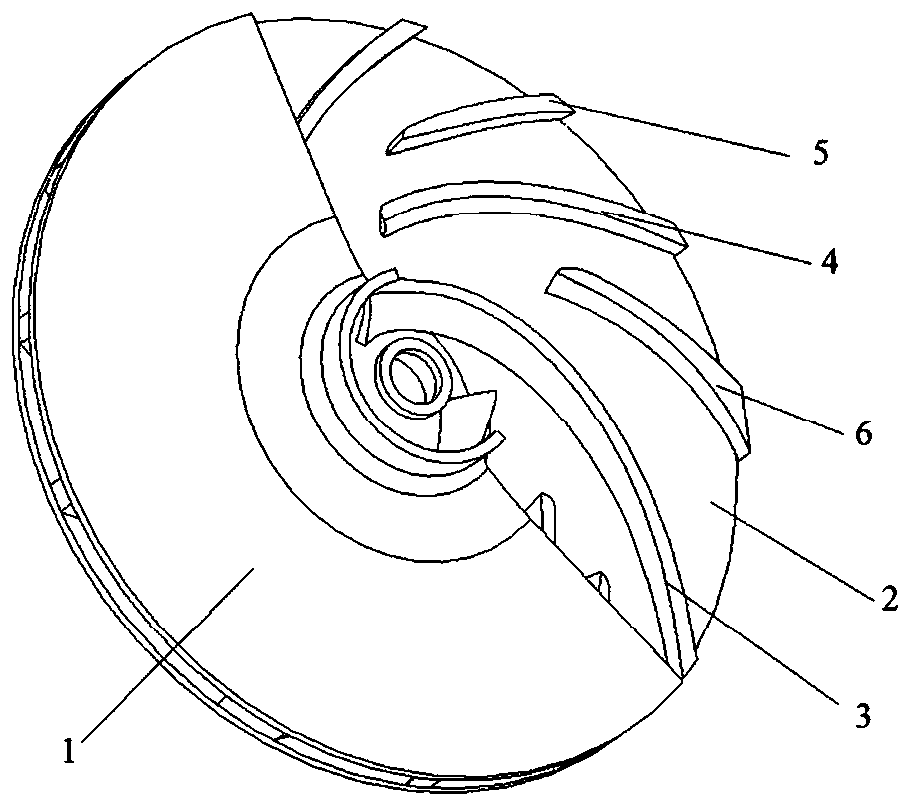
[0025] as attached figure 1 As shown, a pump impeller with secondary splitter blades includes a front cover plate, a rear cover plate, long blades, primary splitter blades, secondary splitter blade 1 and secondary splitter blade 2, all blades are twisted blades, and The number of leaves is 3.

[0026] as attached figure 1 As shown, the long blades are evenly distributed in the circumferential direction of the impeller; the primary splitter blade is located in the flow channel formed by two adjacent long blades; the secondary splitter blade is located in the flow channel between the suction surface of the long blade and the pressure surface of the primary splitter blade; Second...


PUM


Abstract

The invention belongs to the field of design of vane type pumps, and particularly discloses a pump impeller with secondary splitter blades. The pump impeller comprises a front cover plate, a rear cover plate, a long vane, a primary splitter vane, the first secondary splitter vane and a second secondary splitter vane. The vanes are twisted vanes. The pump impeller is provided with the three vanes.The inlet diameter of the primary splitter vane is 0.42-0.46 D2, a vane inlet is offset by 0.4-0.5 theta in the impeller rotation direction, and a vane outlet is offset by 0.4-0.5 theta in the impeller rotation direction. The inlet diameter of the first secondary splitter vane is 0.61-0.64 D2, a vane inlet is offset by 0.2-0.25 theta in the impeller rotation direction, and a vane outlet is offsetby 0.2-0.25 theta in the impeller rotation direction. The inlet diameter of the second secondary splitter vane is 0.65-0.75 D2, a vane inlet is offset by 0.65-0.75 theta in the impeller rotation direction, and a vane outlet is offset by 0.7-0.8 theta in the impeller rotation direction. The vane thickness of the second secondary splitter vane is increased additionally to suction surfaces of the adjacent vanes, and the maximum vane thickness is 1.3-1.6 times the maximum vane thickness of the long vane. The phenomena of flow separation and jet flow-wake in the pump impeller can be suppressed or reduced, and the pump operation efficiency under the low flow working condition is improved.

Description

technical field [0001] The invention belongs to the design field of vane pumps, in particular to a pump impeller with secondary splitter vanes. Background technique [0002] With the rapid development of fields such as petroleum, chemical industry, aerospace, metallurgy and light industry, the performance of pumps is developing in the direction of high speed, high pressure, high efficiency and high power, while low specific speed pumps have the characteristics of small flow and high head, and are widely used in the above industries. [0003] At present, low specific speed pumps mostly adopt a centrifugal pump compound impeller [Application No.: 201520005753.1; Publication No.: CN204419688U] as recorded in Chinese patent documents. number, but the primary splitter impeller still has insufficient blade density. When operating under low flow conditions, the blades have insufficient fluid constraint on the outlet, and the outlet of the impeller is prone to jet-wake, secondary f...

Claims


Application Information

Patent Timeline
Patent Type & Authority Patents(China)
IPC IPC(8): F04D29/22
CPCF04D29/2222
Inventor 王凯芦鑫刘厚林谈明高王勇董亮李钰张子旭景玉成
Owner JIANGSU UNIV
Learn More