
Adhesion testing device

A testing device and adhesive force technology, which is applied in nonlinear optics, instruments, optics, etc., can solve problems such as inaccurate adhesive force testing, and achieve reasonable adhesive and sealing performance effects

Active Publication Date: 2018-08-24
WUHAN CHINA STAR OPTOELECTRONICS TECH CO LTD
View PDF5 Cites 3 Cited by
  • Summary
  • Abstract
  • Description
  • Claims
  • Application Information

AI Technical Summary

Problems solved by technology

[0006] The invention provides a display panel to solve the technical problem of inaccurate testing of the bonding force between the existing color filter substrate and the array substrate

Method used


Image

  • Adhesion testing device
  • Adhesion testing device

Examples


Embodiment Construction

[0027] The following descriptions of the various embodiments refer to the accompanying drawings to illustrate specific embodiments in which the invention may be practiced. The directional terms mentioned in the present invention, such as [top], [bottom], [front], [back], [left], [right], [inside], [outside], [side], etc., are only for reference The orientation of the attached schema. Therefore, the directional terms used are used to illustrate and understand the present invention, but not to limit the present invention. In the figures, structurally similar elements are denoted by the same reference numerals.

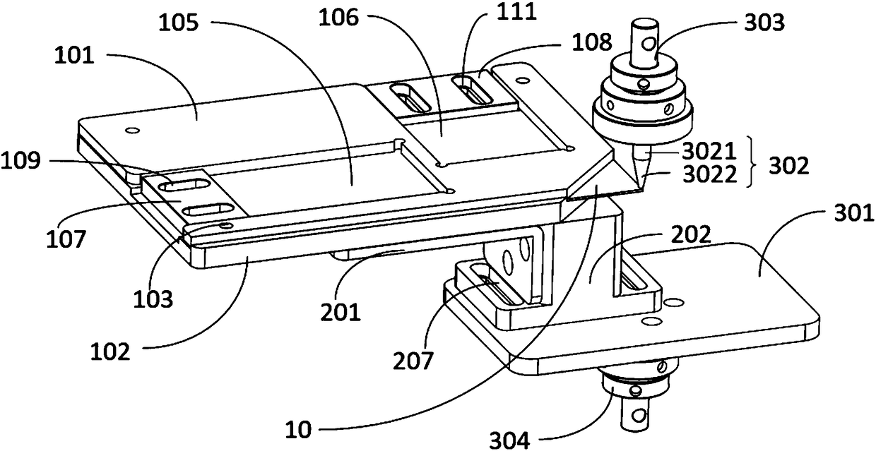
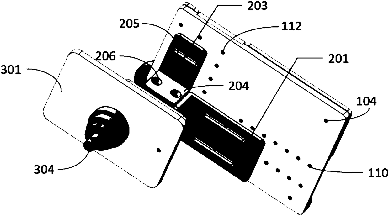
[0028] figure 1 Shown is a structural diagram of an adhesion testing device of the present invention, wherein the device includes a fixing component, a positioning component and a testing component;

[0029] The fixing component is connected to the positioning component, the positioning component is connected to the testing component, and the positioning component is ...


PUM


Abstract

The invention provides an adhesion testing device which comprises a fixing assembly, a positioning assembly and a testing assembly. The fixing assembly comprises a first cover plate and a second coverplate. The first cover plate and the second cover plate are used for fixing a to-be-tested sample. The positioning assembly is used for adjusting the position of the to-be-tested sample and the position of the testing assembly. The testing assembly comprises a force exerting part. Thrust is exerted on the to-be-tested sample by the force exerting part, traditional adhesion testing is converted into thrust testing, the adhesion property of a material is evaluated through the thrust, the external force borne by the product in the film tearing or other operation processes is more accurately simulated, and the adhesiveness and sealing performance of the material are reasonably evaluated.

Description

technical field [0001] The invention relates to a testing device, in particular to a bonding force testing device. Background technique [0002] With the development of liquid crystal display technology, the application of frame glue is becoming more and more extensive. Frame glue is mainly used for bonding liquid crystal display panels. A liquid crystal display panel includes an array substrate and a color filter substrate. The array substrate and the color filter substrate are arranged parallel to each other, and the frame glue is coated on the array substrate and is coated along its edge to form a square frame shape. The liquid crystal is injected into the frame formed by the sealant to form a uniform liquid crystal layer. The color filter substrate is covered on the frame glue, and the frame glue bonds the color filter substrate and the array substrate to each other, and the color filter substrate, frame glue and array substrate form a liquid crystal cell for accommod...

Claims


Application Information

Patent Timeline
Patent Type & Authority Applications(China)
IPC IPC(8): G02F1/13
CPCG02F1/1309
Inventor 韩文马荣
Owner WUHAN CHINA STAR OPTOELECTRONICS TECH CO LTD
Learn More