Device and method for measuring high-pressure leakage of orifice plate

A throttling orifice and high-pressure technology, which is applied in the direction of measuring devices, fuel injection devices, charging systems, etc., can solve the problem of increased leakage risk, affecting the flow of oil in and out of the orifice, and the inability to effectively measure the high pressure of the throttling orifice Oil leakage and other problems, to achieve the effect of good sealing performance, simple and reasonable structure

Active Publication Date: 2018-08-07
CHINA FAW LIMITED WUXI FUEL INJECTIONEQUIP RES INST +1
View PDF5 Cites 0 Cited by
  • Summary
  • Abstract
  • Description
  • Claims
  • Application Information

AI Technical Summary

Problems solved by technology

[0003] At present, diesel engines have higher and higher requirements on the injection pressure of the fuel system. The higher injection pressure significantly increases the risk of leakage between the throttle orifice and the sealing surface of the injector body. There may be leakage between the channel and the control chamber, which will affect the flow of oil in and out of the oil volume hole, and then affect the opening and closing time of the injector, and the higher injection pressure is also a severe test for the structural strength of the throttle orifice itself, so The requirements for sealing and structural strength at the throttle orifice are also getting higher and higher
[0004] However, there is no tightness test for the throttle orifice at present, and the related test is carried out in the fuel injector assembly, which cannot effectively measure the high-pressure oil leakage of the throttle orifice
In addition, limited by the highest pressure that the existing fuel injector assembly can withstand, the test on the fuel injector assembly also determines that the test of the throttle orifice can only be carried out under the highest pressure that the fuel injector can withstand , so it is impossible to test the sealing performance and structural strength of the throttle orifice at a higher pressure (250MPa)

Method used


Image

  • Device and method for measuring high-pressure leakage of orifice plate

Examples


Embodiment Construction

[0024] The present invention will be further described below in conjunction with specific drawings and embodiments.

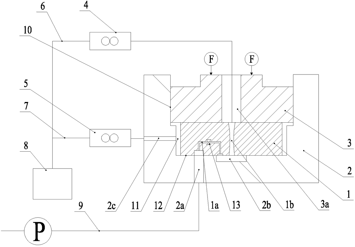
[0025] As shown in the figure: the device for measuring the high pressure leakage of the throttle orifice in the embodiment is mainly composed of the throttle orifice 1, the test orifice seat 2, the pressing block 3, the first flow meter 4, the second flow meter 5, the first flow meter A connecting pipeline 6, a second connecting pipeline 7, an oil tank 8, a test pipeline 9 and a valve 13 etc. are composed.

[0026] like figure 1 As shown, the test orifice seat 2 is provided with a concave cavity, and the bottom surface of the cavity is processed according to the specifications of the orifice seat surface on the injector body, so as to ensure that the throttle orifice 1 is installed on the device and assembled on the injector. The sealing surface formed when it is on the body is consistent. The throttling orifice 1 is placed in the concave cavity and pressed ...


PUM


Abstract

The invention relates to a device and method for measuring high pressure leakage of a throttle orifice plate. The bottom face of a cavity of a test orifice plate seat in the device is machined according to the specification of an orifice plate seat face on a fuel injector body; the throttle orifice plate is placed in the cavity and pressed tight through clamping blocks, a contact face is formed between the lower surface of the throttle orifice plate and the bottom face of the cavity, and an oil return cavity is formed between the peripheral side face of the throttle orifice plate and the inner circumferential side face of the cavity; the inner end of a test oil inlet way communicates with one end of an oil inlet throttle hole in an aligning mode, and the outer end of the test oil inlet way is connected with a test pipeline; a communicating cavity is simultaneously in communication with the other end of the oil inlet throttle hole and the lower end of a central oil hole; the upper end of the central oil hole is connected to an oil tank through a first connecting pipeline, and a first flowmeter is installed on the first connecting pipeline; the inner end of an oil drainage way communicates with the oil return cavity, the outer end of the oil drainage way is connected to the oil tank through a second connecting pipeline, and a second flowmeter is installed on the second connecting pipeline; and a valve is arranged in the oil inlet throttle hole. According to the device and method for measuring high pressure leakage of the throttle orifice plate, a leakproofness test can be independently conducted on the high pressure sealing face of the throttle orifice plate, the test process is simple and flexible, and the test result is accurate and reliable.

Description

technical field [0001] The invention relates to a device and a method for measuring high-pressure leakage of a throttling orifice, and belongs to the technical field of automobile diesel engines. Background technique [0002] With the increasingly stringent requirements for energy conservation and environmental protection, clean and efficient combustion technology for internal combustion engines has become a development trend, which requires good atomization of the fuel injected into the cylinder. Improving the injection pressure of the fuel system can be used as an effective means to improve the fuel atomization effect, and with the advancement of technology and increasingly stringent regulations such as emissions, the injection pressure of the fuel system is also getting higher and higher, such as BOSCH, DENSO and other companies have launched 200MPa High pressure common rail system with above injection pressure. [0003] At present, diesel engines have higher and higher ...

Claims


Application Information

Patent Timeline
Patent Type & Authority Patents(China)
IPC IPC(8): F02M65/00
CPCF02M65/006
Inventor 黄俊俞建达雷超杨翔宇汪祥本徐广兰董庆远胡凯耀刘文超
Owner CHINA FAW LIMITED WUXI FUEL INJECTIONEQUIP RES INST
Why Eureka
Try Eureka