Locking mechanism for electronic lead seal

A locking mechanism and electronic lead sealing technology, applied in the directions of seals, stamps, instruments, etc., can solve the problems of cumbersome operation, unfavorable work efficiency, etc., and achieve the effect of convenient installation and operation and good use effect.

Pending Publication Date: 2018-08-24
JAECELE ELECTRIC
1 Cites 0 Cited by

AI-Extracted Technical Summary

Problems solved by technology

When the above-mentioned seal device is installed and used, seal lead is used to fix the steel wire rope (equivalent to the seal wire in this application) and the...

Method used

Further improvement, described lead seal hole 11 is the through hole that runs through described housing 1, and this through hole end has the bell mouth that gradually shrinks from outside to inside caliber, arranging bell mouth is conducive to wire to pass through described The lead-sealed hole 11 improves the convenience of the threading operation. Specifically, the through hole is sequentially connected by the first bell mouth section 111, the cylindrical hole section 112 and the second bell mouth section 113, the gap 12 is arranged in the middle of the cylindrical hole section 112, and the cylindrical hole section The ratio of the length of 112 to the total length of the through hole is 1:6-7.
In the present embodiment, the first positionin...

Abstract

The invention discloses a locking mechanism for an electronic lead seal. The locking mechanism comprises a shell, wherein a lead seal hole, from which a lead seal line can run through, is formed in the shell; the locking mechanism is arranged in the shell and is used for locking the lead seal line in the lead seal hole; a notch is formed in the middle of the lead seal hole; the locking mechanism comprises a locking sheet which abuts against and is used for pressing the lead seal line and an elastic part for offering locking elasticity to the locking sheet; the locking sheet is rotatably arranged in the shell via a connecting shaft; and under the action of the elastic part, the free end of the locking sheet extends into the lead seal hole from the notch. The electronic lead seal provided bythe invention is reasonable in structure and convenient to mount and use; and the electronic lead seal is excellent in service effect.

Application Domain

StampsIdentification means +1

Technology Topic

EngineeringLocking mechanism

Image

  • Locking mechanism for electronic lead seal
  • Locking mechanism for electronic lead seal

Examples

  • Experimental program(1)

Example Embodiment

[0016] The following describes the specific structure of the present invention in conjunction with the accompanying drawings of the specification:
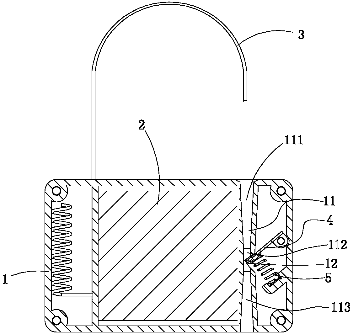
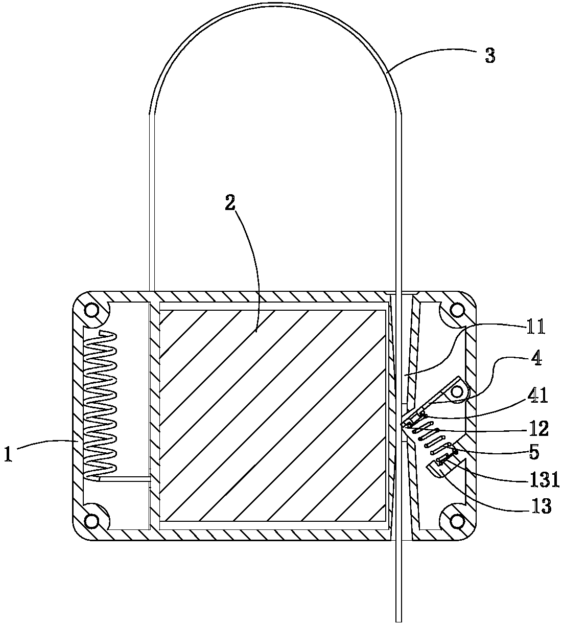
[0017] A locking mechanism for electronic seals, such as figure 1 with figure 2 As shown, it includes a housing 1 with a sealing hole 11 for the sealing line 3 to pass through, and a locking mechanism is provided in the housing for locking the sealing line 3 in In the lead sealing hole 11, a gap 12 is provided in the middle of the lead sealing hole 11, and the locking mechanism includes a locking piece 4 for pressing the sealing line 3 and providing a locking elastic force for the locking piece 4 The elastic member 5, the locking piece 4 is rotatably installed inside the housing 1 through a connecting shaft, and the free end of the locking piece 4 extends into the notch 12 under the action of the elastic member 5 The lead seal hole 11. When the above-mentioned electronic seal is installed, the free end of the seal line 3 is inserted into the seal hole 11 after bypassing the object to be locked. During the insertion process, the end of the seal line 3 causes the locking piece 4 The force causes the locking piece 4 to overcome the force of the elastic component 5 and rotate. When the seal line 3 is inserted in place, the elastic component 5 exerts a locking elastic force on the locking piece 4 to press and lock the seal line 3. Prevent the sealing line 3 from exiting from the sealing hole.
[0018] In this embodiment, the elastic member 5 is a spiral compression spring, one end of the compression spring abuts on the locking piece 4, and the other end abuts on the compression spring positioning seat 13 in the housing 1 As a deformation, the elastic member 5 can also be a torsion spring in actual operation.
[0019] In this embodiment, the compression spring positioning seat 13 is formed with a first positioning structure for positioning one end of the compression spring, and the locking piece 4 is formed with a second positioning structure for positioning the other end of the compression spring. Specifically, the first positioning structure is a positioning groove 131, and the second positioning structure is a positioning boss 41. Through the positioning groove 131 and the positioning boss 41, one end of the compression spring is located in the positioning groove 131, and the other end is sleeved on the positioning boss 41, so that the compression spring can play a good role. Positioning function to ensure the effectiveness and stability of the installation and use of the compression spring.
[0020] As a further improvement, the lead sealing hole 11 is a through hole penetrating through the housing 1, and the end of the through hole has a bell mouth whose diameter gradually decreases from outside to inside. 11. Improve the convenience of threading operation. Specifically, the through hole is formed by sequentially connecting a first flared section 111, a cylindrical hole section 112, and a second flared section 113, the gap 12 is provided in the middle of the cylindrical hole section 112, and the cylindrical hole section The ratio of the length of 112 to the total length of the through hole is 1:6-7.
[0021] Obviously, the above-mentioned embodiments of the present invention are merely examples to clearly illustrate the present invention, and are not intended to limit the implementation of the present invention. For those of ordinary skill in the art, other changes or changes in different forms can be made on the basis of the above description. There is no need and cannot give an exhaustive list of all implementation methods. And these obvious changes or variations derived from the essential spirit of the present invention still belong to the protection scope of the present invention.

PUM

no PUM

Description & Claims & Application Information

We can also present the details of the Description, Claims and Application information to help users get a comprehensive understanding of the technical details of the patent, such as background art, summary of invention, brief description of drawings, description of embodiments, and other original content. On the other hand, users can also determine the specific scope of protection of the technology through the list of claims; as well as understand the changes in the life cycle of the technology with the presentation of the patent timeline. Login to view more.

Similar technology patents

Food dicing machine

Owner:HOME CULTURE APPLIANCES SHENZHEN

Lamp

ActiveCN105318284AEasy to install and operatesave space and material
Owner:SELF ELECTRONICS CO LTD

Classification and recommendation of technical efficacy words

  • Good effect
  • Easy to install and operate

Self-propelling camellia oleifera fruit-picking machine

InactiveCN102668817AEasy to install and operateGood adaptability to picking environment
Owner:CENTRAL SOUTH UNIVERSITY OF FORESTRY AND TECHNOLOGY +1
Why Eureka
Try Eureka