Punch with automatically regulating balancer

An automatic adjustment and balancer technology, used in manufacturing tools, presses, etc., can solve problems such as seizure, large differences in setting values, and affecting the accuracy of stamping products.

Inactive Publication Date: 2018-08-28
CHIN FONG MACHINE IND
View PDF4 Cites 0 Cited by
  • Summary
  • Abstract
  • Description
  • Claims
  • Application Information

AI Technical Summary

Problems solved by technology

[0004] In addition, the punch press is generally equipped with a punch display screen (not shown in the figure) for displaying and setting various operating parameters of the punch press, but this kind of punch press still has the following disadvantages: Estimate the weight of the slider group 12, mold 15, connecting rod 14 and crankshaft 13 based on theoretical values ​​to set the output of the balancer 17, and sometimes even set and adjust the balancer 17 based on personal experience and the movement of the slider group 12 The theoretically estimated weight is often quite different from the actual weight, and the personal experience of different debuggers is different, and the set value is often different. When replacing the mold 15, it may be forgotten to readjust the output of the balancer 17 or due to Due to limited experience, it is impossible to adjust it correctly. The above situations may lead to inaccurate output setting of the balancer 17, which will cause the local strength load of the connection between the copper alloy 16 and the crankshaft 13 to be too heavy, making the alloy copper 16 easy to wear; The local gap between copper 16 and crankshaft 13 is too small, resulting in heat generation and even seizure; local heat generation will generate additional energy consumption, which will cause insufficient input power of the main motor and affect the precision of stamping products

Method used


Image

  • Punch with automatically regulating balancer
  • Punch with automatically regulating balancer
  • Punch with automatically regulating balancer

Examples


Embodiment Construction

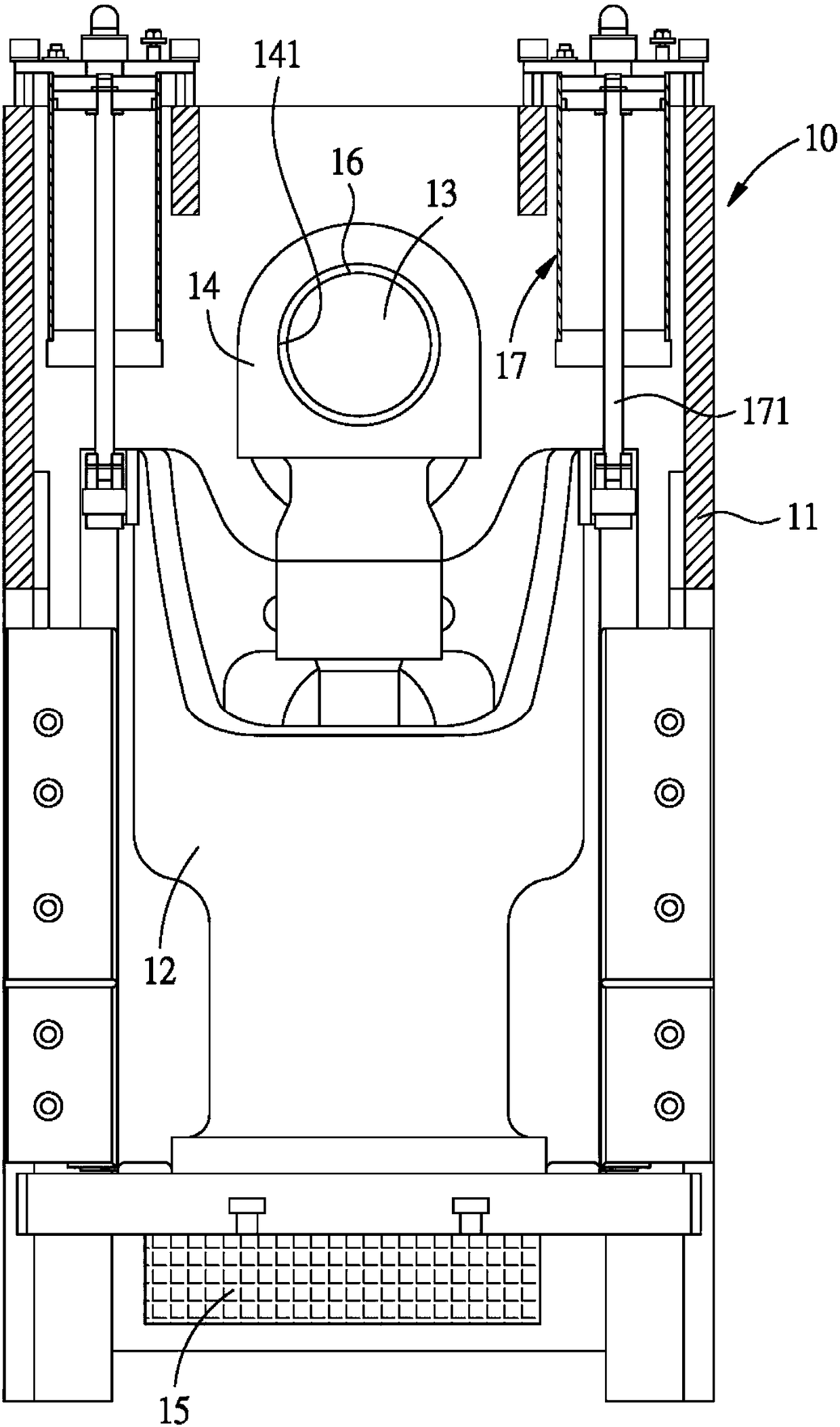
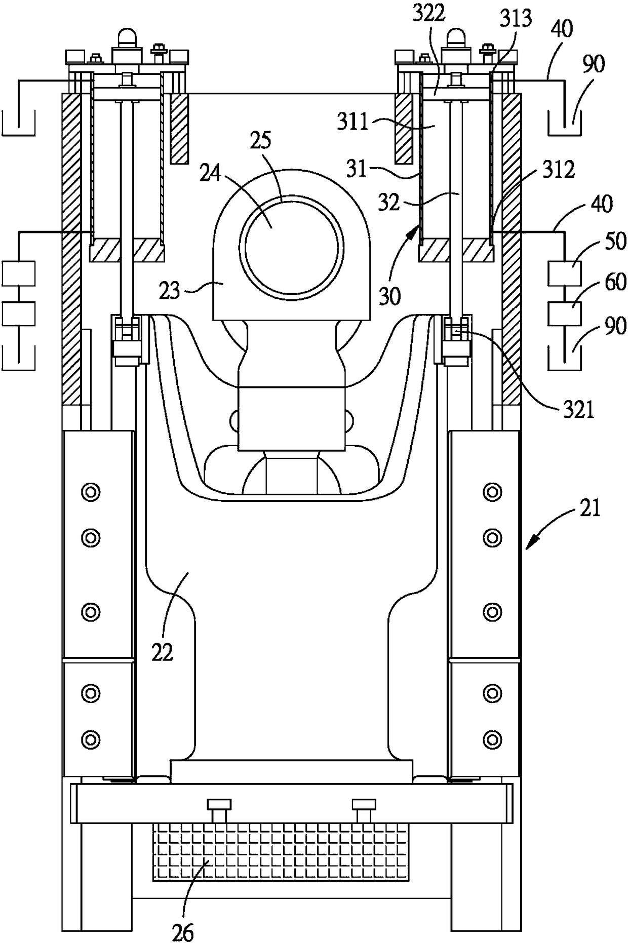
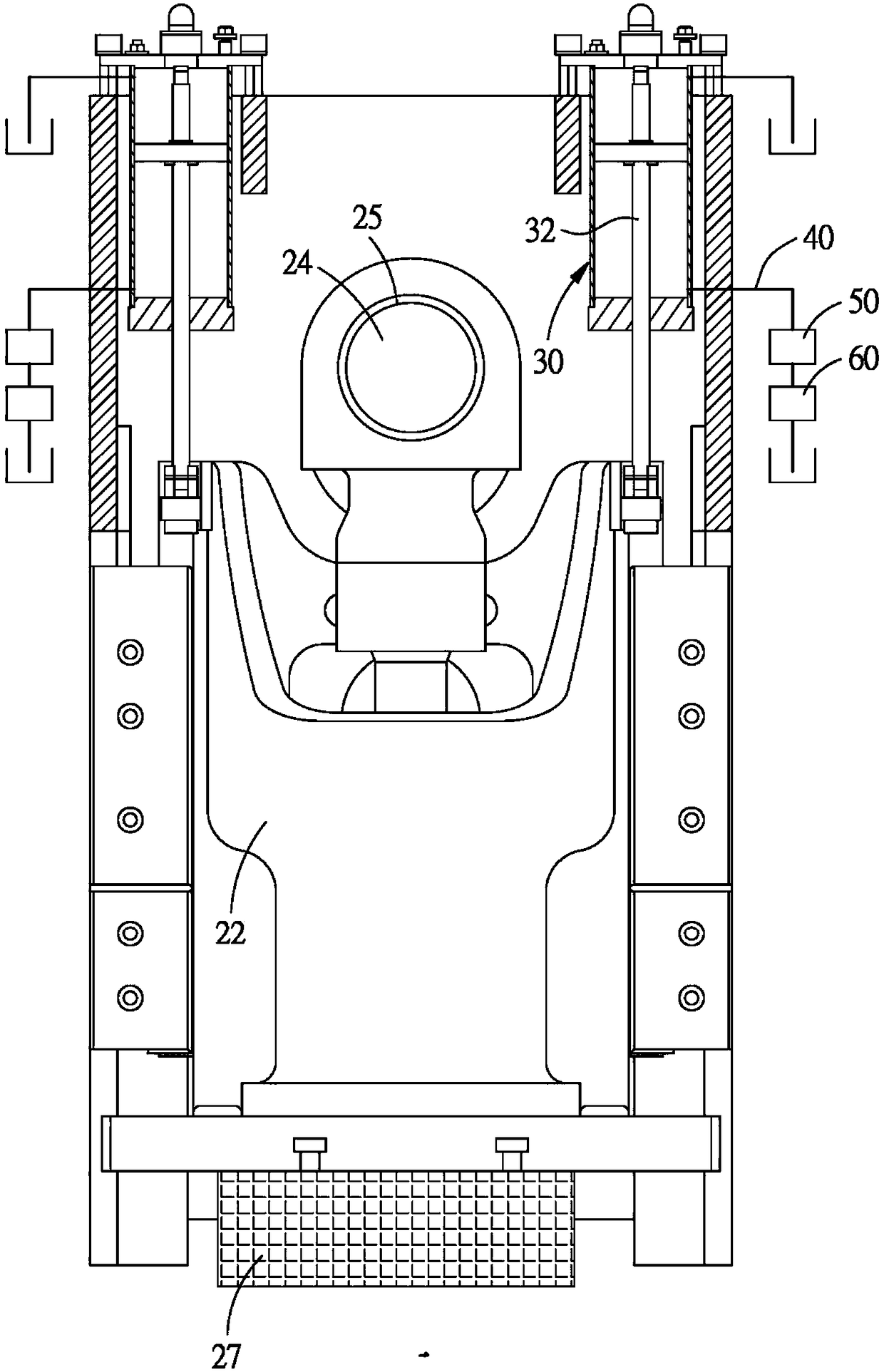
[0039] Please refer to Figure 2 to Figure 4 As shown, the embodiment of the present invention provides a punch press with an automatic balancer, which is mainly composed of a machine base 21, a slider group 22, a connecting rod 23, a crankshaft 24, a copper alloy 25, and a Self-adjusting balancer consisting of:

[0040] The slider set 22 is arranged on the base 21 so as to be able to reciprocate up and down; in this embodiment, a first mold 26 with a first weight is arranged on the lower end surface of the slider set 22 .

[0041] The connecting rod 23 is connected to drive the slider group 22 .

[0042] The crankshaft 24 is rotatably inserted on the connecting rod 23 to drive the connecting rod 23 to move.

[0043] The copper alloy 25 is arranged between the crankshaft 24 and the connecting rod 23 .

[0044] Because the machine base 21, the slider group 22, the connecting rod 23, the crankshaft 24, and the copper alloy 25 are all known components, and their configuration ...


PUM


Abstract

The invention discloses a punch with an automatically regulating balancer. The punch mainly consists of a bedplate, a sliding block group, a connecting rod, a crankshaft, a copper bush, and the automatically regulating balancer. The automatically regulating balancer includes two balance units, an air pressure pipeline, a pressure sensing unit, and a pressure control unit. According to the invention, the pressure sensing unit is combined with the pressure control unit, so that when bar bodies of the balance units are at a second position, the pressure control unit can control pressure in the air pressure pipeline to keep the bar bodies of the balance units at a first position. Therefore, the crankshaft has the best and the most stable contact effect with the copper bush, and the purpose that the punch is in a best working state can be achieved.

Description

technical field [0001] The present invention is related to the balancer of the punching machine, in particular to a punching machine with an automatic adjustment balancer. Background technique [0002] refer to figure 1 As shown, it is an existing punch press 10 with a balancer, comprising: a base 11, a slide block group 12 that can reciprocate up and down on the base 11, a crankshaft 13, a crankshaft 13 connected to the slider The connecting rod 14 of the block group 12 and a driving unit (not shown) that are power connected to the crankshaft 13. By driving the crankshaft 13 to rotate through the drive unit, the slider group 12 can be driven to drive the mold 15 to reciprocate up and down to carry out stamping operation on the material. [0003] Generally speaking, the upper side of the connecting rod 14 is provided with a transverse through hole 141, and the crankshaft 13 is rotatably connected with the connecting rod 14 through the through hole 141. There is alloy copp...

Claims


Application Information

Patent Timeline
Patent Type & Authority Applications(China)
IPC IPC(8): B30B15/00
CPCB30B15/0064
Inventor 蔡志仁
Owner CHIN FONG MACHINE IND
Why Eureka
Try Eureka