Self-adaptive anti-falling device and current collector thereof

An anti-shedding and self-adaptive technology, applied in the field of current receivers, can solve the problems of reducing the service life of the sliding shoe, poor contact, damage to the car body and line, etc., to achieve stable contact performance, prevent excessive wear, and stabilize the current effect.

Pending Publication Date: 2022-08-09
湖南中通电气股份有限公司
View PDF1 Cites 0 Cited by
  • Summary
  • Abstract
  • Description
  • Claims
  • Application Information

AI Technical Summary

Problems solved by technology

The current receiver needs to keep in contact with the power supply rail during the process of taking current, but factors such as the installation position error of the current receiver, the manufacturing error of the power supply rail, assembly error, wear and other factors are likely to cause the sliding shoe of the current receiver and the surface of the power supply rail to be non-parallel to each other The occurrence of the problem not only causes poor contact and makes the power supply of the current receiver unstable, but also causes partial wear of the slipper shoe of the current collector, which reduces the service life of the slipper shoe, increases economic losses, and shortens the vehicle maintenance cycle
[0003] The Chinese patent with the application number 201721087263.6 discloses a double-swing bar insulated current collector, which is equipped with a sliding shoe buffer device, but the buffer device is made of rubber or polyurethane, etc., and this type of buffer device itself has the risk of aging. At the same time, under the action of a large external force, the buffer device will break from the middle, causing the sliding shoe to fall off, easily causing damage and failure of the current collector, and even causing damage to the car body and lines, which poses a large safety hazard

Method used


Image

  • Self-adaptive anti-falling device and current collector thereof
  • Self-adaptive anti-falling device and current collector thereof
  • Self-adaptive anti-falling device and current collector thereof

Examples


Embodiment 1

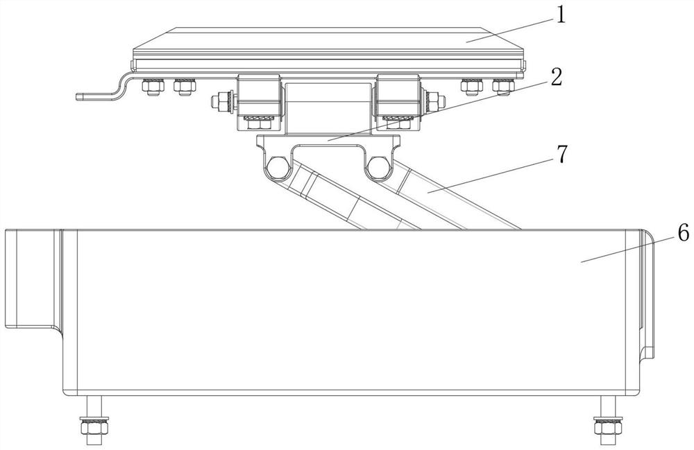
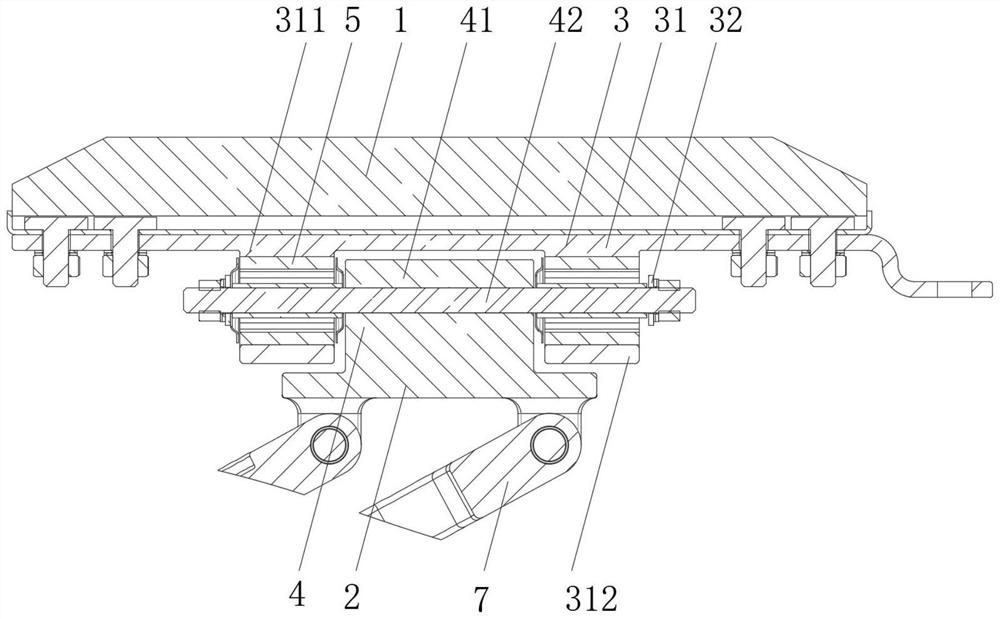
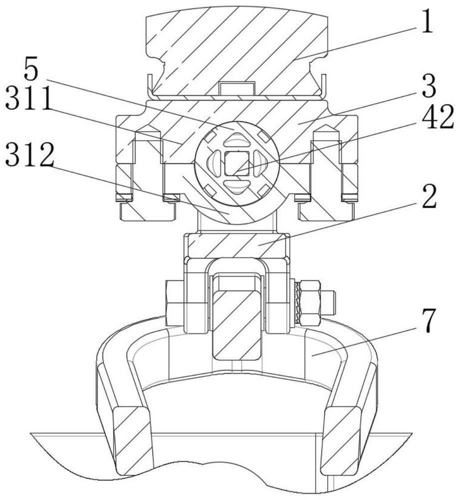
[0029] like figure 2 and image 3 As shown, the adaptive anti-falling device of this embodiment is connected between the sliding shoe 1 and the swing rod base 2, and the adaptive anti-falling device includes a connecting seat 3 arranged on the sliding shoe 1 and a connecting seat 3 arranged on the swinging rod base The mounting seat 4 on the 2, the connecting seat 3 and the mounting seat 4 are fitted and connected, and there is a gap between the two fitting positions. In this embodiment, the gap is parallel to the arrangement direction of the sliding shoe 1, and the gap is filled with Elastic padding 5. This setting method not only has a fitting connection relationship, and avoids the accident that the sliding shoe 1 and the swing rod base 2 no longer have a connection after the elastic filler 5 is aged and broken, resulting in the accident of the sliding shoe 1 being disengaged; it is also different from the traditional rigid connection. , through the combination of the ga...

Embodiment 2

[0037] This embodiment is basically the same as Embodiment 1, and the difference is that, such as Figure 7 As shown, in this embodiment, the connecting seat 3 is a ring-shaped structure arranged at the bottom of the sliding shoe 1, the mounting seat 4 is a cylindrical structure 43 arranged on the swing rod base 2, and the lower half circle 33 of the connecting seat 3 penetrates through The inner hole of the mounting seat 4 is detachably connected to the upper half ring 34, the upper half ring 34 and the lower half ring 33 of the connecting seat 3 sandwich the top wall of the cylindrical structure 43, and the sandwiched gap is filled with an elastic filler 5 . In this embodiment, the disengagement limit of the connecting seat 3 is realized by the ring shape surrounding the cylindrical structure 43 , and the connecting seat 3 can swing around the lower half circle 33 to a certain extent under the action of the elastic filler 5 and the gap. and floats radially along the cylindr...

Embodiment 3

[0039] This embodiment is basically the same as Embodiment 2, and the difference is that, such as Figure 8 As shown, in this embodiment, the mounting seat 4 is a bar-shaped hole 44 arranged on the swing rod base 2, and the connecting seat 3 is a bar-shaped member 35 arranged at the bottom of the sliding shoe 1, the bar-shaped member 35 and the bar-shaped hole 44 are parallel to the arrangement direction of the sliding shoe 1 , the inner wall section of the strip hole 44 is larger than that of the strip member 35 , and the gap between the two is filled with an elastic filler 5 .

[0040] In this embodiment, in order to limit the separation between the two, the two side walls of the strip hole 44 adjacent to the bottom wall are provided with a plurality of concave clamping grooves 441. The position corresponding to 441 is provided with a protruding rib 351 , and the rib 35 is clamped into the slot 441 by the rib 351 to realize the limit perpendicular to the arrangement directio...


PUM


Abstract

The invention discloses a self-adaptive anti-falling device and a current collector thereof.The self-adaptive anti-falling device is connected between a sliding shoe and a swing rod base and comprises a connecting base arranged on the sliding shoe and a mounting base arranged on the swing rod base, the connecting base and the mounting base are connected in an embedded mode, and a gap exists between the connecting base and the mounting base at the embedded position; and elastic fillers are filled in the gaps, so that the connecting seat can swing relative to the mounting seat around an axis parallel to the arrangement direction of the sliding shoes when being stressed, and can float relative to the mounting seat along the direction vertical to the swinging axis. The self-adaptive anti-falling device has the advantages of simplicity, practicability, high connection strength, swing allowance, capability of making up contact errors between the sliding shoes and the power supply rail and the like. The current collector using the self-adaptive anti-falling device has the advantages of being stable in electricity taking performance, prolonging the service life of the sliding shoes, prolonging the maintenance cycle of a vehicle and the like.

Description

technical field [0001] The invention relates to the field of current receivers, in particular to an adaptive anti-dropping device and a current receiver thereof. Background technique [0002] The current collector is a device that is installed on the rail train and dynamically draws current by contacting the rigid power supply rail to supply power to the train. The current collector needs to keep in contact with the power supply rail during the current extraction process, but the installation position error of the current collector, the manufacturing error of the power supply rail, assembly error, wear and other factors may easily cause the current collector slipper and the power supply rail surface to be non-parallel to each other. The problem occurs, which not only causes poor contact and unstable power supply of the current receiver, but also causes eccentric wear of the current receiver slipper, reduces the service life of the slipper, increases economic losses, and shor...

Claims


Application Information

Patent Timeline
Patent Type & Authority Applications(China)
IPC IPC(8): B60L5/38
CPCB60L5/38B60L2200/26
Inventor 汪永明程卫群万理杨开伟韦丽娟
Owner 湖南中通电气股份有限公司
Why Eureka
Try Eureka