Ceramic jar lifting clamp

A technology of ceramic cylinders and ropes, which is applied in conveyors, manual conveying devices, transportation and packaging, etc., can solve the problems of inconvenient movement of ceramic cylinders.

Inactive Publication Date: 2018-08-28
遂宁福家科技有限公司
View PDF7 Cites 0 Cited by
  • Summary
  • Abstract
  • Description
  • Claims
  • Application Information

AI Technical Summary

Problems solved by technology

[0003] The object of the present invention is to overcome the disadvantage of inconvenient movement of the existing ceramic cylinders, and provide a ceramic cylinder lifting clamp that is easy to move, hereinafter referred to as the lifting clamp

Method used


Image

  • Ceramic jar lifting clamp
  • Ceramic jar lifting clamp

Examples


Embodiment Construction

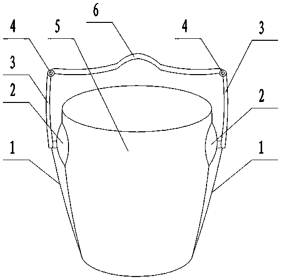
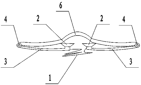
[0009] figure 1 In the middle, it is the picture of the situation when the jacket is put on the ceramic cylinder and it is to be lifted. A lifting rope 1 is placed in the middle of the bottom of the ceramic cylinder 5 . Lifting rope 1 is placed on ceramic cylinder 5 bottoms that one section has the color that is easy to identify, and the distance of two sucker 2 center equates between the two ends of the lifting rope section with color. The lower ends of the two lifting rods 3 are respectively connected with a sucker 2, and the sucker 2 is sucked and buckled on both sides above the outer wall of the ceramic cylinder, which are mutually symmetrical positions. The lower ends of the two lifting rods 3 are respectively connected with the two ends of the lifting rope 1, and the lifting rope has been tightened. The two ends of the handle 6 are provided with hinges 4 . The upper ends of the two handles 3 are hinged to the two ends of the handle 6 respectively. The lighter ceramic...


PUM


Abstract

A ceramic jar lifting clamp comprises a handle, lifting rods, lifting ropes, suction cups and hinges. The upper ends of the two lifting rods are hinged to the two ends of the handle. The lower ends ofthe lifting rods are connected with the suction cups. The two ends of the lifting rope are connected to the lower ends of the two lifting rods. When the ceramic jar lifting clamp is used, a ceramic jar is moved obliquely, and the segment marked with colors of the lifting rope is put right in the middle of the bottom of the ceramic jar; the handle is lifted, the lifting rope is tensioned, and thesuction cups at the lower ends of the two lifting rods are symmetrically sucked and buckled to the upper portion of the outer wall of the ceramic jar; and the lifting rope is fixed; the ceramic jar can be lifted away by a person or carried away by two persons. The ceramic jar with the smooth surface can be conveniently lifted away.

Description

technical field [0001] The invention belongs to the field of ceramic cylinder moving tools, in particular to a lifting clip for ceramic cylinders. Background technique [0002] Some of the existing ceramic jars are used for pickling vegetables, adorning sauce, adorning water, and planting flowers and plants. However, ceramic cylinders are often relatively large, and generally can hold more than 30 kilograms of objects. Although it is pre-installed in one place, once you want to change another place, especially for flowers and plants, you have to move it outside for a period of time, put it in the sun and fresh air for a certain period of time, and then move it back. The ceramic cylinder slips up and down, and people often have nowhere to start when they move it, and they are powerless to use, which is very laborious and inconvenient. Contents of the invention [0003] The object of the present invention is to overcome the disadvantages of inconvenient movement of the exi...

Claims


Application Information

Patent Timeline
Patent Type & Authority Applications(China)
IPC IPC(8): B65G7/12
CPCB65G7/12B65G2201/0235
Inventor 邹家福
Owner 遂宁福家科技有限公司
Why Eureka
Try Eureka