Carrier control method and device

A technology of a carrying device and a control method, applied in the directions of transportation and packaging, conveyor control device, conveyor objects, etc., can solve the problems of increasing the handling cost, increasing the difficulty of handling, and consuming labor, and achieving the effect of reducing the difficulty of handling.

Active Publication Date: 2021-05-14
CHANGZHOU COLLEGE OF INFORMATION TECH
View PDF7 Cites 0 Cited by
  • Summary
  • Abstract
  • Description
  • Claims
  • Application Information

AI Technical Summary

Problems solved by technology

In the process of transporting goods, it is inevitable to carry out loading and unloading operations on the car. Because the transport vehicle has a certain height, the traditional handling method usually uses a crane for operation, which increases the difficulty of handling and increases the cost of handling. At the same time consume a lot of labor

Method used


Image

  • Carrier control method and device
  • Carrier control method and device
  • Carrier control method and device

Examples


Embodiment 1

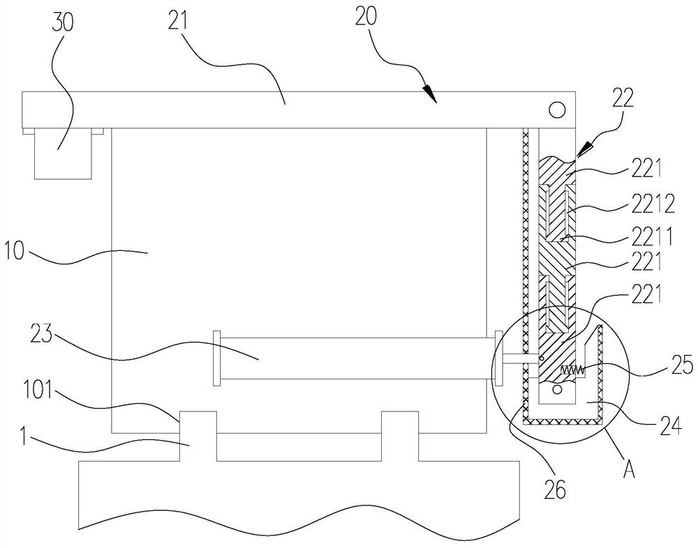
[0049] see figure 1 , figure 2 , the invention provides a carrying device, which is used for carrying a car. The carrier device includes a carrier 10 and a carrier assembly 20 mounted on the carrier 10 , and the transported vehicles complete loading and unloading work through the carrier assembly 20 .

[0050] The vehicle 10 is movably arranged on the road. In this embodiment, the vehicle 10 is an unmanned transport vehicle. Specifically, the lower end surface of the carrier 10 is concavely provided with two slide grooves 101, and the road surface is convexly provided with two guide rails 1 matching with the slide grooves 101, and the carrier 10 is erected on the guide rails 1 through the slide grooves 101. While the tool 10 is moving, the guide rail 1 is slidably connected with the slide groove 101 .

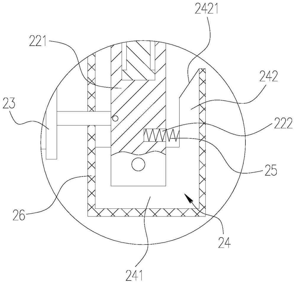
[0051] The carrying component 20 includes a load board 21 , a telescopic mechanism 22 , a supporting mechanism 23 , a guide plate 24 , an elastic member 25 and a telescopic...

Embodiment 2

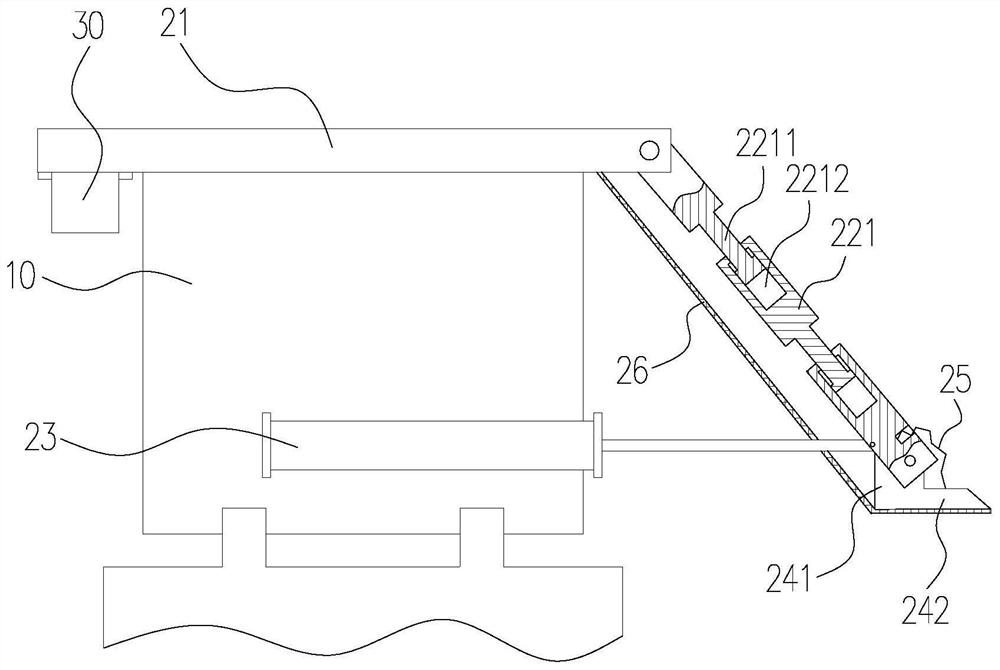
[0064] see Figure 4 The difference between the carrying device provided in the second embodiment and the carrying device in the first embodiment lies in that the supporting mechanism 23 of the second embodiment has a different structure.

[0065] Specifically, in this embodiment, the supporting mechanism 23 includes a motor (not shown) fixedly installed on one side of the carrier 10, a gear 231 installed on the output shaft of the motor, and a rack meshed with the gear 231 232. The motor is a forward and reverse motor, the rack 232 is slidingly connected to the carrier 10 , and one end of the rack 232 is rotationally connected to the telescopic plate 221 on the telescopic mechanism 22 away from the carrying plate 21 . When in use, start the motor, the motor drives the gear 231 to rotate, and then the gear 231 drives the rack 232 to slide relative to the carrier 10. It is stretched or shortened under the action, thereby making the guide plate 24 open or close synchronously. ...


PUM


Abstract

The invention discloses a method for controlling a carrying device. The method is applied to the carrying device. The carrying device includes a carrier and a carrying assembly, and the carrying assembly includes a carrying plate, a telescopic mechanism, a supporting mechanism, a guide plate, an elastic member, and a telescopic member. , the bearing plate is installed on the top of the carrier, the telescopic mechanism includes a plurality of sequentially connected telescopic plates, each adjacent two telescopic plates move relatively telescopically, and the telescopic plate at one end of the telescopic mechanism is connected to the load plate in rotation, The supporting mechanism is set on the carrier and pushes against the telescopic plate at the other end of the telescopic mechanism. The guide plate is rotatably connected to the telescopic plate away from the load plate. The elastic member is telescopically arranged between the telescopic plate and the guide plate. The other end of the telescopic piece is connected to the guide plate; when receiving a loading request, controlling the supporting mechanism to push against the telescopic plate can make the guide plate open under the pull of the telescopic piece; this reduces the difficulty of handling the car , the cost effect.

Description

technical field [0001] The present invention relates to the technical field of transportation, in particular, to a control method and device for a transportation device. Background technique [0002] An unmanned transport vehicle is an automatically controlled ground vehicle with its own drive, which can transport cars, etc. to a designated location according to a formulated route. In the process of transporting goods, it is inevitable to carry out loading and unloading operations on the car. Because the transport vehicle has a certain height, the traditional handling method usually uses a crane for operation, which increases the difficulty of handling and increases the cost of handling. Consumed a large amount of labor simultaneously. Contents of the invention [0003] The technical problem to be solved by the present invention is: in order to overcome the above-mentioned problems existing in the prior art, a control method and device for a carrier are now provided, and ...

Claims


Application Information

Patent Timeline
Patent Type & Authority Patents(China)
IPC IPC(8): B65G43/00B65G25/06
CPCB65G25/065B65G43/00
Inventor 姚裕宝
Owner CHANGZHOU COLLEGE OF INFORMATION TECH
Why Eureka
Try Eureka