A hydraulic mud discharge system

A mud system and hydraulic technology, which is used in the field of sludge removal and discharge at the bottom of sedimentation tanks or thickeners, can solve problems such as high energy consumption, and achieve short sludge discharge cycle, high sludge discharge efficiency and low energy consumption. Effect

Active Publication Date: 2020-06-26
中山市民东有机废物处理有限公司
View PDF12 Cites 0 Cited by
  • Summary
  • Abstract
  • Description
  • Claims
  • Application Information

AI Technical Summary

Problems solved by technology

Therefore, in the actual operation process of the scheme provided by this patent, it also needs to consume a large amount of energy

Method used


Image

  • A hydraulic mud discharge system
  • A hydraulic mud discharge system
  • A hydraulic mud discharge system

Examples


Embodiment 1

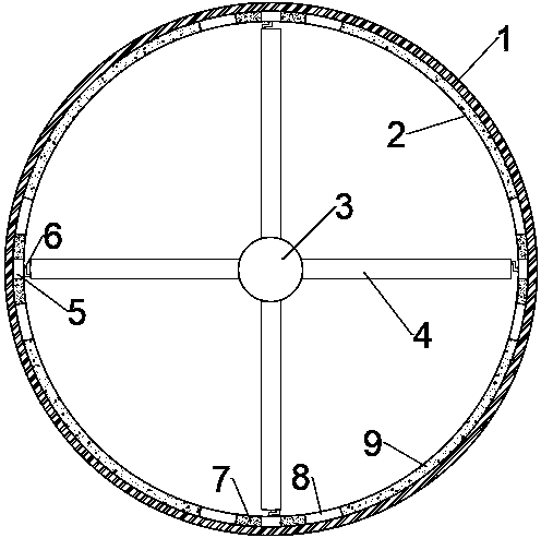
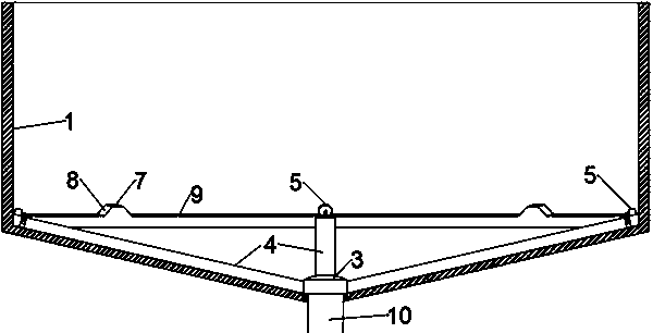
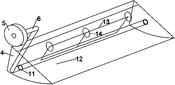
[0025] Embodiment 1: as Figure 1-6 As shown, a hydraulic mud discharge system is arranged at the bottom of the sedimentation tank 1, including a rotating mud collecting cap 3, a mud suction arm 4, a pulley 5, a pulley rod 6, a pulley platform 2 and a mud discharge pipe 10, wherein The mud discharge pipe 10 is fixedly arranged at the center of the bottom of the sedimentation tank 1, and communicates with the outside of the pond. The rotating mud collecting cap 3 is arranged on the upper end of the mud discharging pipe 10, and the inner end of the mud suction arm 4 is fixedly arranged on the rotating mud collecting cap. 3, the inner cavity of the suction arm 4 is in fluid communication with the inner cavity of the rotary suction cap 3, and the pulley 5 is rotatably connected to the outer end of the suction arm 4 through a pulley rod 6, and the suction arm 4 Suction mud gate 12 is provided on it.

[0026] The rotating mud collecting cap 3 is rotationally sealed with the upper e...

Embodiment 2

[0038] Embodiment 2: different from embodiment 1, such as Figure 7-9 As shown, the upper end of the dredging gate 12 is hinged on the upper part of the dredging arm 4 through a hinge 16, and its lower end is movably overlapped on the upper edge of the dredging plate 17, and the two sides of the dredging gate 12 are respectively vertical The side plate 21 of the suction gate is fixedly provided, wherein, the side plate 21 of the suction gate located on one side of the rotary mud collecting cap 3 is provided with an opening 22 of the side plate of the suction gate to serve as the sewage in the inner cavity of the suction arm 4. The opening for the muddy water to flow into the rotating mud collecting cap 3, the size and location of the side plate opening 22 of the dredging gate are just so that when the dredging gate 12 is at the maximum opening, its side is closed.

[0039] The low platform 9 has a certain length, so that the pulley 5 can slide along the low platform 9 for a ce...


PUM


Abstract

The invention provides a hydraulic sludge discharging system. The hydraulic sludge discharging system comprises a rotatable sludge-suction arm which is provided with an openable and closable sludge-suction gate, wherein the interior of the sludge-suction arm is rotatably provided with a pulley rod; one end of the pulley rod is connected with a pulley which can slide to move on a pulley platform located at the bottom part of the periphery of a sedimentation pool; the pulley platform is provided with a protrusion or a recess; and when the pulley slides over the protrusion or the recess, the opening or closing state of the sluge-suction gate can be changed, so hydraulic sludge discharging is realized. According to a scheme of the invention, the internal water pressure of the sedimentation pool is fully utilized to discharge sludge, and no additional suction power is needed; meanwhile, an indexing rotation mode can be adopted, and a complete sludge-discharging process can be realized without the need of rotating in a circle, so sludge-discharging resistance and energy consumption are greatly reduced.

Description

technical field [0001] The invention relates to a hydraulic mud discharge system and a mud discharge method thereof. It specifically involves the removal and discharge of sludge at the bottom of sedimentation tanks or thickeners. It can quickly and efficiently discharge the sludge deposited at the bottom of the sedimentation tank or thickener with low running resistance. Background technique [0002] Sedimentation tanks and thickeners are indispensable basic equipment in industrial processes such as sewage treatment and mineral processing. Both of them use the principle of gravity sedimentation to reduce the flow rate of water in a large pool space to make it approach to The gentle laminar flow allows the particles to settle freely and achieve solid-liquid separation. At present, there are three main means to enhance the settlement effect. One is to add flocculants to the solid-containing liquid to promote the aggregation of fine particles and accelerate the settlement; T...

Claims


Application Information

Patent Timeline
Patent Type & Authority Patents(China)
IPC IPC(8): B01D21/24
CPCB01D21/245
Inventor 刘洋
Owner 中山市民东有机废物处理有限公司
Why Eureka
Try Eureka