Eureka AIR delivers breakthrough ideas for toughest innovation challenges, trusted by R&D personnel around the world.

Anti-theft lock

An anti-theft lock and lock body technology, applied in the field of anti-theft locks, can solve problems such as unfavorable anti-theft

Pending Publication Date: 2018-08-31
李浩远
View PDF0 Cites 1 Cited by
  • Summary
  • Abstract
  • Description
  • Claims
  • Application Information

AI Technical Summary

Problems solved by technology

[0003] With the development of technology, in order to enhance the anti-theft effect, some existing anti-theft door locks have canceled the outer handle, and the technology of fingerprint recognition is used to control the connecting rod to drive the transmission mechanism in the lock body to make the corresponding action of unlocking or locking. When the outer panel is opened, the lock body is exposed, because although the outer handle is canceled, but because the inner handle still exists, it is easy for people to destroy the lock body from the position where the outer handle is canceled (that is, the position where the connecting rod is installed). The purpose of forcibly unlocking is not conducive to anti-theft

Method used


Image

  • Anti-theft lock
  • Anti-theft lock
  • Anti-theft lock

Examples


Embodiment Construction

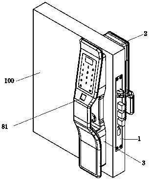
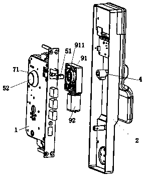
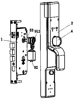
[0029] as attached figure 1 to attach image 3 A kind of anti-theft lock shown, it comprises lock body 1, inner panel 2, outer panel 3, inner handle 4, inner handle 4 is linked with lock body 1 through connecting rod 5, and anti-theft lock is provided with the drive controlled by control device The device is used to drive the connecting rod 5, and the connecting rod 5 has a main rod 51 for interlocking with the lock body 1.

[0030] The first end of the main rod 51 is provided with a cylindrical end 52 for preventing the connecting rod 5 from passing through the lock body 1. The connecting rod 5 breaks away from the locking structure of the lock body 1 . The peripheral wall and end surface of the terminal 52 are smooth, so that the violent lockpicker has nowhere to focus and destroys the lock body 1 from the position where the outer handle is removed (that is, the position where the connecting rod 5 is installed) and forcibly unlocks, thereby improving the force of violent l...


PUM


Abstract

The invention discloses an anti-theft lock which comprises a lock body, an inner panel, an outer panel and an inner handle. The inner handle is connected to the lock body by a connecting rod in a linkage mode. The anti-theft lock is provided with a driving device controlled by a controlling device to drive the connecting rod. The connecting rod is provided with a main rod used for linkage with thelock body. An end socket is arranged at the first end of the main rod, wherein the end socket is cylindrical and used for preventing the connecting rod from penetrating through the lock body. The circumference wall and the end face of the end socket are smooth surfaces. A locking structure is arranged at the second end of the main rod to prevent the connecting rod from leaving the lock body. Thecircumference wall and the end face of the end socket are arranged to be smooth surfaces, and a violent lock picker has nowhere to focus so that destroys the lock body and breaks the lock violently from the position of a canceled outer handle( the position of mounting the connecting rod). Difficulty of prying the lock violently is increased.

Description

technical field [0001] The invention relates to an anti-theft lock. Background technique [0002] The main components of the anti-theft door lock include a lock body, an inner panel, an outer panel, an inner handle and an outer handle. Installed on the inner panel and the outer panel, the inner handle and the outer handle are respectively connected to the lock body through a connecting rod (square steel). The rotation of the inner handle or the outer handle drives the corresponding connecting rod to rotate, so that the connecting rod drives the lock The transmission mechanism in the body makes the corresponding action of unlocking or locking. [0003] With the development of technology, in order to enhance the anti-theft effect, some existing anti-theft door locks have canceled the outer handle, and the technology of fingerprint recognition is used to control the connecting rod to drive the transmission mechanism in the lock body to make the corresponding action of unlockin...

Claims


Application Information

Patent Timeline
Patent Type & Authority Applications(China)
IPC IPC(8): E05B3/00E05B15/00
CPCE05B3/00E05B15/00E05B15/0033
Inventor 李浩远
Owner 李浩远
Why Eureka
Eureka Blog
Learn More