CT perfusion protocol targeting

A targeted and perfusion scanning technology, applied in radiation beam guiding devices, medical science, diagnosis, etc., can solve problems such as increasing doses

Pending Publication Date: 2018-08-31
KONINKLJIJKE PHILIPS NV
View PDF4 Cites 1 Cited by
  • Summary
  • Abstract
  • Description
  • Claims
  • Application Information

AI Technical Summary

Problems solved by technology

However, shuttle mode increases dose and may miss peak enhancement during ingestion

Method used


Image

  • CT perfusion protocol targeting
  • CT perfusion protocol targeting
  • CT perfusion protocol targeting

Examples


Embodiment Construction

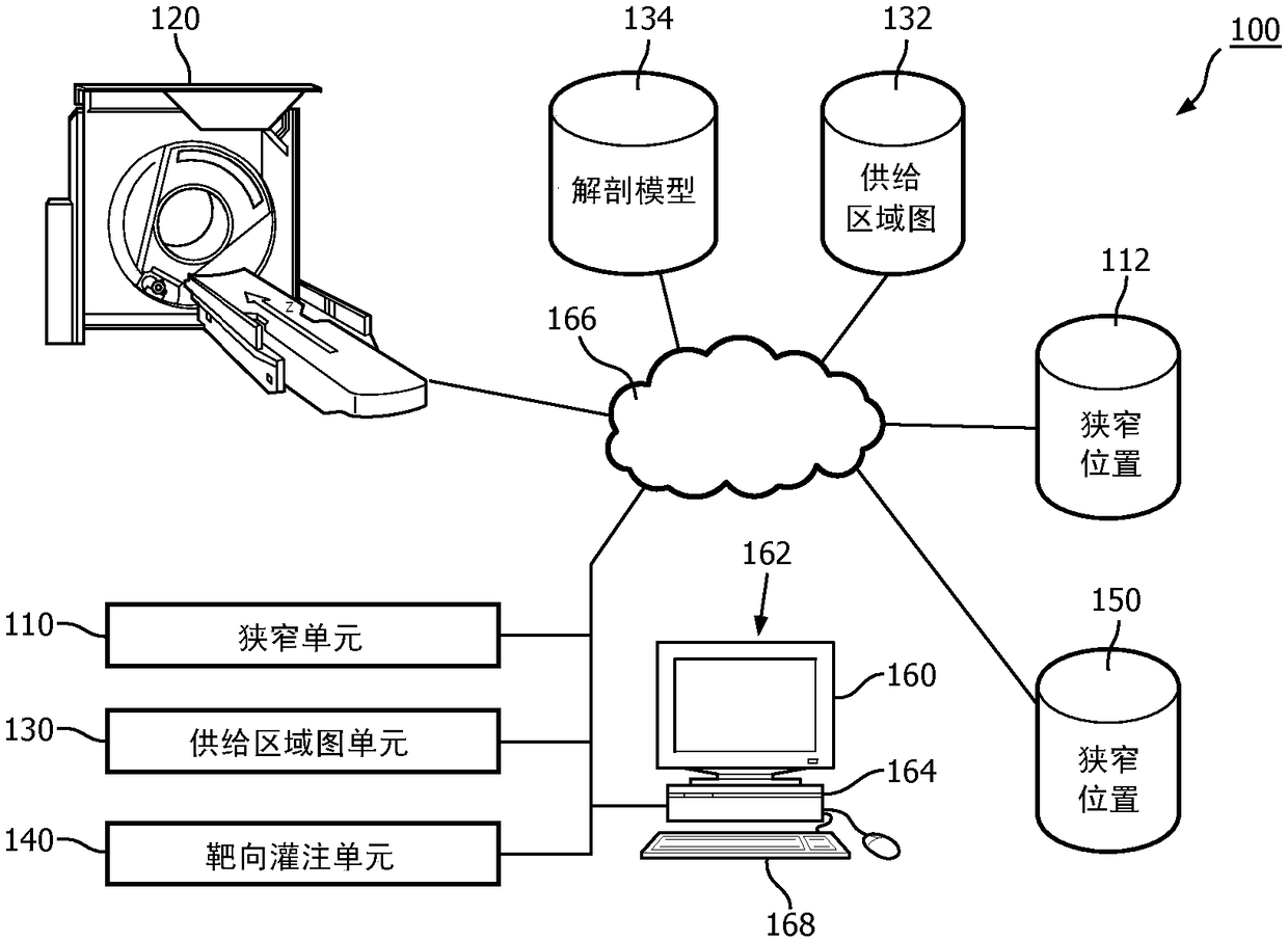
[0014] first reference figure 1 , schematically illustrates a targeted perfusion protocol system 100 . The stenosis unit 110 identifies a stenosis location 112 in the patient's organ, such as the heart. A stenosis is an abnormal narrowing of the lumen of an artery, as in narrowing of the coronary arteries of the heart. In one embodiment, stenosis is identified from previous volumetric images of the organ (eg, previous imaging studies). In one embodiment, the stenosis may include a stent location. In one embodiment, the stenosis unit 110 controls a scanning device 120 such as a CT scanner, X-ray scanner, magnetic resonance (MR) scanner, combinations thereof, etc. to scan the heart according to an angiography protocol. The scanning device 120 generates the location(s) of the stenosis 112 according to an angiography protocol using techniques known in the art, for example in a volumetric image of the organ. For example, CT angiography (CTA) protocols scan the entire heart in a...


PUM


Abstract

A system (100) for a targeted perfusion scan includes a computed tomography (CT) scanner (120), a feeding territory map (132) and a targeted perfusion unit (140). The CT scanner (120) performs a perfusion scan of a portion of tissues of an organ. The feeding territory map (132) maps arterial locations of an arterial vessel tree to spatially located organ tissues of the organ fed by the arterial locations. The targeted perfusion unit (140) includes one or more processors (164) configured to determine targeted coverage (200) from a location of a stenosis (112, 210) and the feeding territory map,and to control the CT scanner to perform the perfusion scan according to the determined targeted coverage.

Description

technical field [0001] The following generally relates to medical imaging with particular application to computed tomography (CT) perfusion scans, such as perfusion scans of organs such as the heart, liver or brain. Background technique [0002] CT perfusion protocols use CT scanning equipment to scan the myocardium of the heart during uptake of an administered contrast agent to identify and diagnose myocardial defects. During a perfusion scan, the CT gantry rotates sections of the heart across the field of view at the same axial position, or z-axis, to observe increased contrast in the tissue. An X-ray source emits X-rays that pass through tissue and are detected by radiation detectors. The detected X-rays are reconstructed into a CT image, which is then fused to the perfusion image. The same axial position corresponds to a position along the patient's longitudinal axis, eg the patient remains in the same position relative to the plane of the rotating gantry. The increas...

Claims


Application Information

Patent Timeline
Patent Type & Authority Applications(China)
IPC IPC(8): A61B6/03A61B6/00
CPCA61B6/032A61B6/486A61B6/503A61B6/545A61B6/507A61B6/08A61B6/469A61B6/504A61B6/488A61B6/5205A61B6/54
Inventor S·普雷弗尔哈尔H·施米特H·尼克基施
Owner KONINKLJIJKE PHILIPS NV
Why Eureka
Try Eureka