CT system with synthetic view generation

a synthetic view and scanner technology, applied in tomography, instruments, applications, etc., can solve the problems of affecting the image quality of ceph, occupying space for each device, and affecting the diagnostic quality of the image, so as to achieve the effect of reducing the dosage, reducing the dose, and good diagnostic quality

Active Publication Date: 2006-10-26
XORAN TECH
View PDF19 Cites 48 Cited by
  • Summary
  • Abstract
  • Description
  • Claims
  • Application Information

AI Technical Summary

Benefits of technology

[0009] Because of the inherent noise reduction in the synthetic projection process, a very low dose CT scan can be used. The CT scan itself would be considered to be well below what is considered diagnostic quality as a CT scan, but produces a synthetic projection that is very good diagnostic quality. Additionally, dosage can be further reduced by varying the dosage of certain images and / or by varying the angular spacing between certain images during the acquisition of the CT scan.

Problems solved by technology

Each of these devices occupies space, possibly even a dedicated room.
The cephalometric x-ray (or “ceph scan”) equipment in particular occupies a large space.
Otherwise, the distortion from incident angles of the x-rays will distort the ceph image.

Method used


Image

  • CT system with synthetic view generation
  • CT system with synthetic view generation
  • CT system with synthetic view generation

Examples


Embodiment Construction

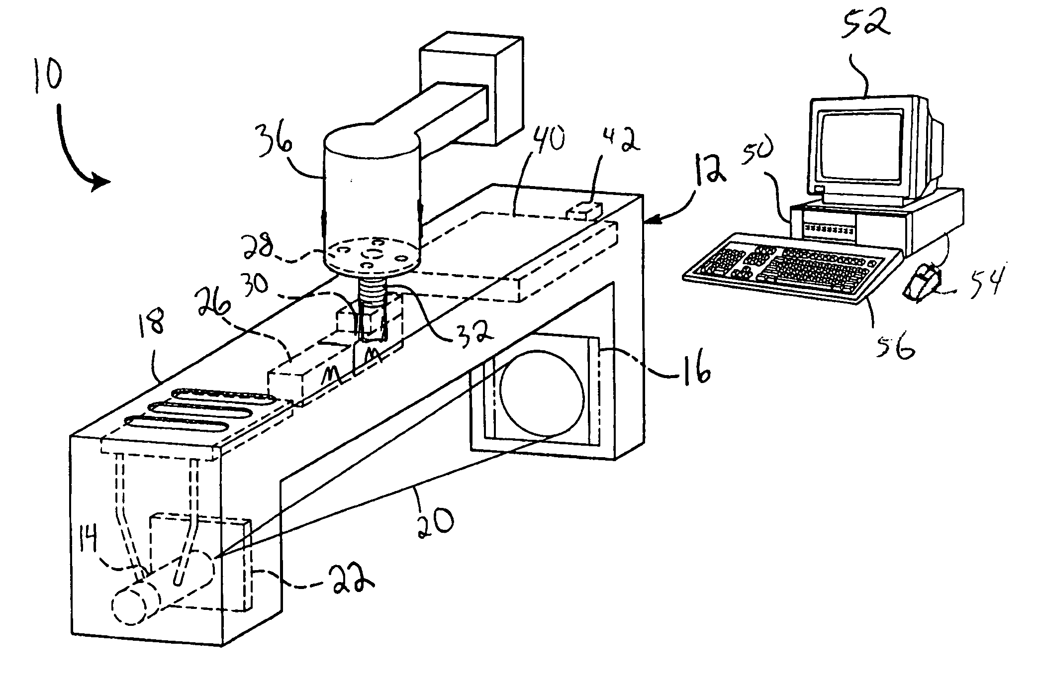
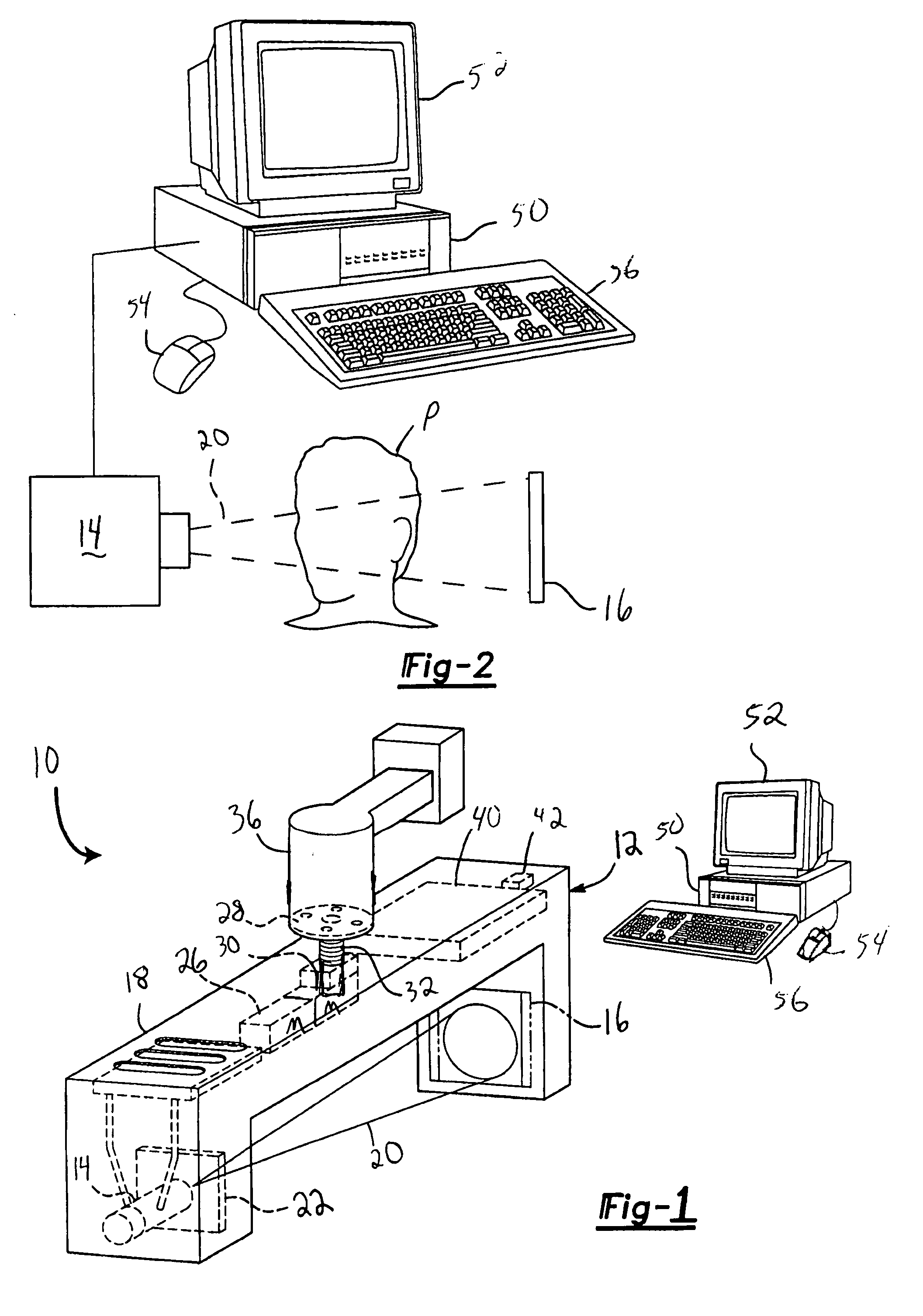
[0026] One possible embodiment of a scanning system 10 according to the present invention is shown in FIG. 1. The scanning system 10 includes CT scanner 12 having an x-ray source 14 and x-ray detector 16 mounted opposite one another on a gantry 18. Suitable CT scanners 12 are known, but would preferably utilize a cone-beam x-ray source 14 and a flat-panel detector 16. The detector 16 has a converter for converting x-rays 20 from the x-ray source 14 to visible light and an array of photodetectors behind the converter. A collimator 22 may be mounted in the gantry 18 in front of the x-ray source 14.

[0027] A first motor 26 is mounted in the gantry 18 for rotating the gantry 18 relative to a mounting plate 28. The first motor 26 may directly drive the mounting plate 28, or a gear box may be provided between the first motor 26 and mounting plate 28. The mounting plate 28 may be mounted to an arm 36 supported above the floor. A second motor 30 may be provided to selectively move the gantr...


PUM


Abstract

A CT scanner system provides projection-like images of a patient volume. After a CT scan is obtained and a three-dimensional model of the patient is created, any synthetic view can be generated by choosing any array of projection lines, e.g. between a point and a surface (a flat plane, curved plane, spherical, etc) or between two surfaces (parallel or not) and summing across the projection lines. The synthetic projections can mimic certain traditional views, such as a ceph scan, Water's view, Caldwell's projection, etc or can provide a new view that is impossible or impractical with traditional x-ray equipment, such as a perfect parallel projection, or a projection that does not pass all the way through the patient.

Description

[0001] This application claims priority to U.S. Provisional Application Ser. Nos. 60 / 674,638, filed Apr. 25, 2005 and 60 / 771,797, filed Feb. 9, 2006.BACKGROUND OF THE INVENTION [0002] The present invention relates to a CT scanner system. [0003] There are many types of specialized x-ray equipment or arrangements each dedicated to providing a specific view or type of x-ray projection. For example, such as panoramic dental x-rays, Water's view x-rays, Caldwell's projection, and cephalometric x-rays are each typically provided by a different type of x-ray machine or arrangement. Each of these devices occupies space, possibly even a dedicated room. [0004] The cephalometric x-ray (or “ceph scan”) equipment in particular occupies a large space. Maxillofacial surgeons, orthodontists and other doctors use cephalometrics to diagnose, plan and predict maxillofacial surgeries, orthodontic treatment and other treatments that could affect the shape and appearance of the face. One important part o...

Claims


Application Information

Patent Timeline
Patent Type & Authority Applications(United States)
IPC IPC(8): A61B6/14
CPCA61B6/032A61B6/14A61B6/465A61B6/5223A61B6/467A61B6/469A61B6/501A61B6/466
Inventor SUKOVIC, PREDRAGCLINTHORNE, NEALSTAYMAN, JOSEPH WEBSTERRAKIC, MIODRAG
Owner XORAN TECH
Why Eureka
Try Eureka