Rotational X ray device for phase contrast imaging

a phase contrast imaging and x-ray technology, applied in tomography, applications, instruments, etc., can solve the problems of not directly spatially resolved patterns, and the inability to achieve pixel size of existing x-ray detectors, so as to minimize the loss of x-ray photons

Inactive Publication Date: 2013-10-22
KONINK PHILIPS ELECTRONICS NV
View PDF15 Cites 52 Cited by
  • Summary
  • Abstract
  • Description
  • Claims
  • Application Information

AI Technical Summary

Benefits of technology

[0017]The diffractive optical element DOE may be any device that is able to generate the desired interference pattern when irradiated with X-rays. Preferably, the DOE comprises a phase grating, i.e. a grating the lines of which have negligible absorption but substantial phase shift, thus minimizing the loss of X-ray photons.

Problems solved by technology

A problem of the described approach is that the feasible pixel size of existing X-ray detectors is (much) larger than the distance between the maxima and minima of the interference pattern.
These patterns can therefore not directly be spatially resolved.
The necessary movement of optical elements is however a nontrivial mechanical task, particularly if it has to be done fast and with high accuracy, as would be required if phase contrast imaging shall be applied in a medical environment.

Method used


Image

  • Rotational X ray device for phase contrast imaging
  • Rotational X ray device for phase contrast imaging
  • Rotational X ray device for phase contrast imaging

Examples


Embodiment Construction

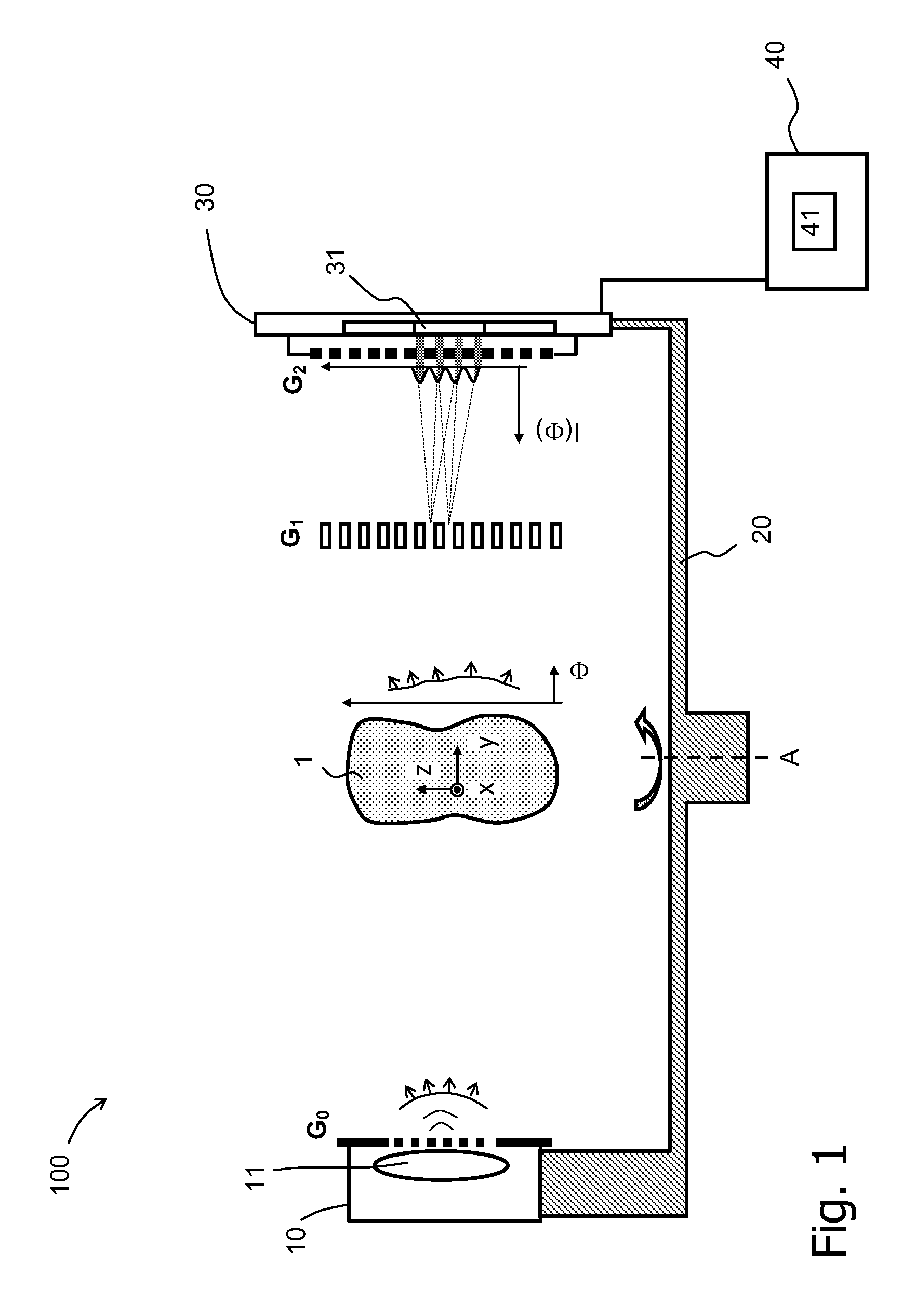
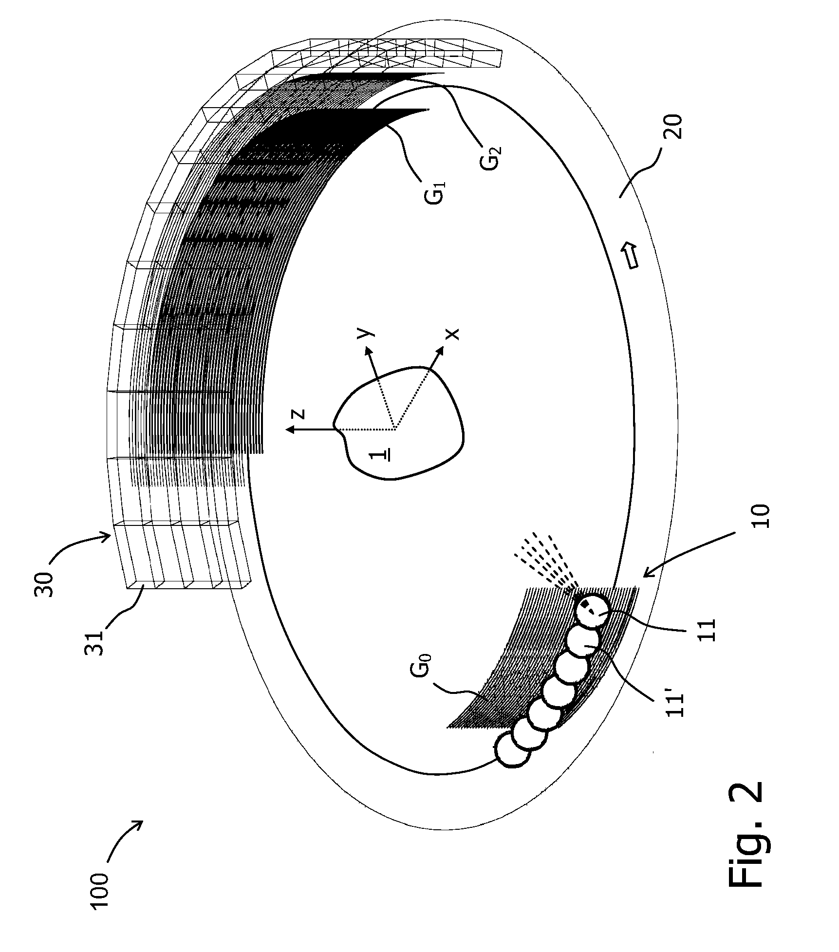
[0046]Phase contrast X-ray imaging aims at the measurement of the phase shift of X-rays as they pass through an object. The benefit of phase sensitive measurements is that the phase contrast is potentially orders of magnitude higher than the absorption contrast (cf. A. Momose, “Phase sensitive imaging and phase tomography using X-ray interferometers”, Optics Express 11(19), 2003; T. Weitkamp et al., “X-ray phase imaging with a grating interferometer”, Optics Express 13(16), 2005). Initially a major shortcoming of phase sensitive methods was that X-ray sources with a very narrow bandwidth were required. This shortcoming could however be overcome by using standard X-ray tubes with a special filter to achieve a bandwidth of 10%-20% (cf. F. Pfeiffer et al., “Phase retrieval and differential phase contrast imaging with low-brilliance X-ray sources”, Nature Physics 2, pp 258-261, 2006). When combined with phase stepping, phase sensitive measurements and total X-ray absorption information ...


PUM


Abstract

The invention relates to a rotational X-ray device (100), for example a CT scanner, for generating phase contrast images of an object (1). In a particular embodiment of the device (100), a plurality of X-ray sources (11), an X-ray detector (30), and an analyzer grating (G2) are attached to a rotatable gantry (20), while a ring-shaped phase grating (G1) is stationary. The X-ray sources are disposed such that X-rays first pass an object under study before traversing the phase grating (G1) and subsequently the analyzer grating (G2). This is achieved by either shifting the X-ray sources axially with respect to the ring-shaped phase grating (G1) or by disposing the X-ray sources in the interior of the ring. Moreover, the phase grating (G1) and the analyzer (G2) shall have spatially varying relative phase (and / or periodicity), for example realized by line grids that are tilted with respect to each other. During the rotation of the gantry (20), the synchronized activation of X-ray sources (11) allows to generate projection images of an object (1) from the same viewing angle with different relative positions (and therefore phases) between the phase grating (G1) and the analyzer (G2).

Description

FIELD OF THE INVENTION[0001]The invention relates to a method and a rotational X-ray device for generating phase contrast X-ray images of an object. Moreover, it relates to a computer program product incorporating such a method.BACKGROUND OF THE INVENTION[0002]While classical X-ray imaging measures the absorption of X-rays caused by an object, phase contrast imaging aims at the detection of the phase shift X-rays experience as they pass through an object. According to a design that has been described in literature (T. Weitkamp et al., “X-ray phase imaging with a grating interferometer”, Optics Express 13(16), 2005), a phase grating is placed behind an object to generate an interference pattern of intensity maxima and minima when the object is irradiated with (coherent) X-rays. Any phase shift in the X-ray waves that is introduced by the object causes some characteristic displacement in the interference pattern. Measuring these displacements therefore allows to reconstruct the phase ...

Claims


Application Information

Patent Timeline
Patent Type & Authority Patents(United States)
IPC IPC(8): A61B6/03
CPCA61B6/032A61B6/4007A61B6/4291A61B6/484G21K2207/005
Inventor BREDNO, JOERG
Owner KONINK PHILIPS ELECTRONICS NV
Why Eureka
Try Eureka