Display device
一种显示装置、显示区域的技术,应用在辨认装置、静态指示器、阴极射线管指示器等方向,能够解决无法表现颜色等问题,达到抑制阶梯式晃动显示的效果
- Summary
- Abstract
- Description
- Claims
- Application Information
AI Technical Summary
Problems solved by technology
Method used
Image

Examples
Embodiment approach
[0031] Hereinafter, embodiments of the present invention will be described in detail with reference to the drawings. In the drawings, the same reference numerals are assigned to the same or corresponding parts, and description thereof will not be repeated. In addition, in order to facilitate understanding and description, in the drawings referred to below, the configuration is simplified or schematically shown, or some constituent members are omitted. In addition, the dimensional ratio between the constituent members shown in each drawing does not necessarily represent an actual dimensional ratio.
[0032] In the following description, a case where the display device is a liquid crystal display will be described. However, the display device of the present invention is not limited to a liquid crystal display, and may be an organic EL display, a plasma display, or the like.
[0033] The display device is, for example, a smartphone. However, the display device is not limited t...
no. 1 Embodiment approach
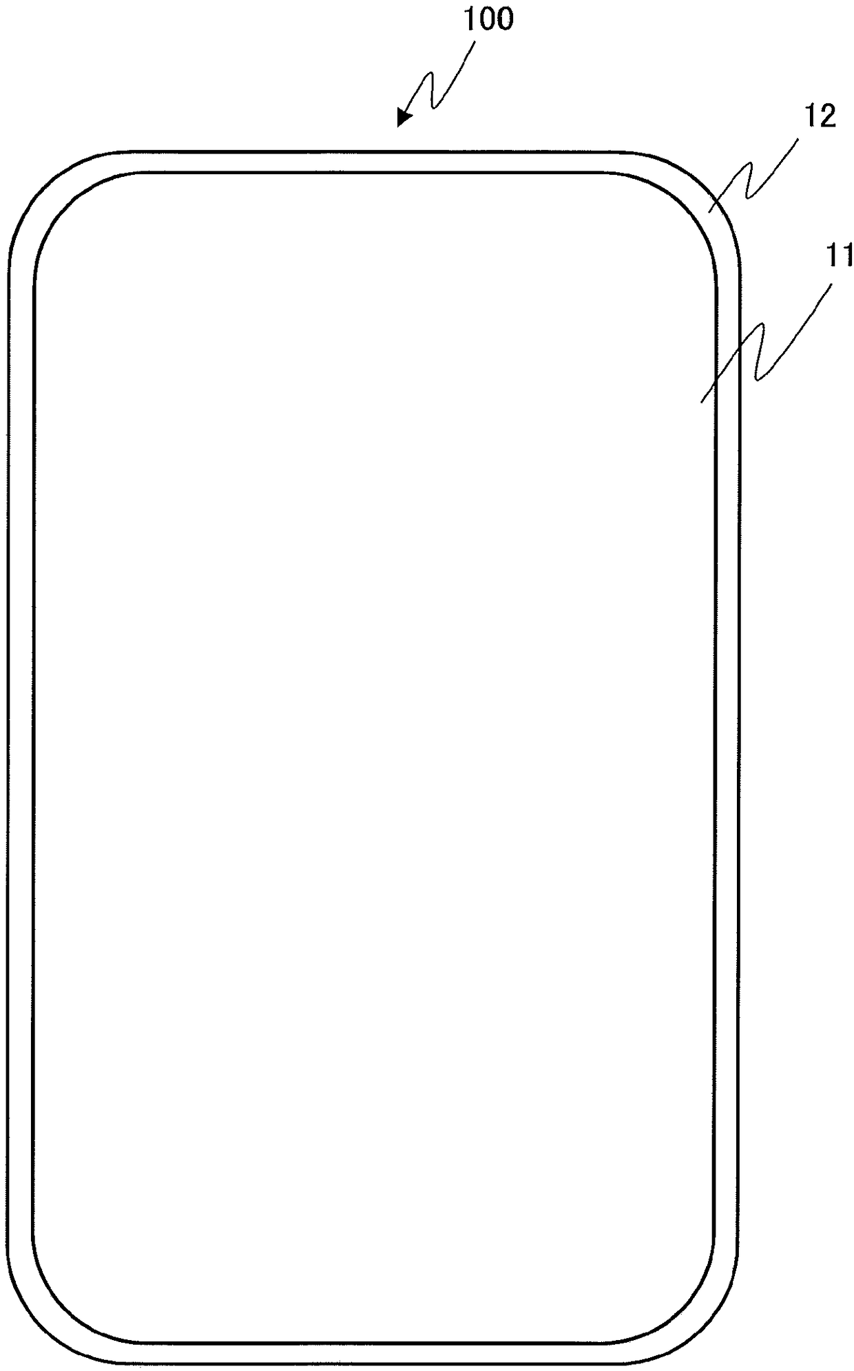
[0035] figure 1 It is a figure showing the appearance shape of the display device 100 of 1st Embodiment. The display device 100 according to the first embodiment has a non-rectangular shape, and its corners are not right angles, but R-shaped with smooth curves. Similarly, the image display area 11 is also a non-rectangular shape with R-shaped corners. The outside of the display area 11 is a non-display area 12 .
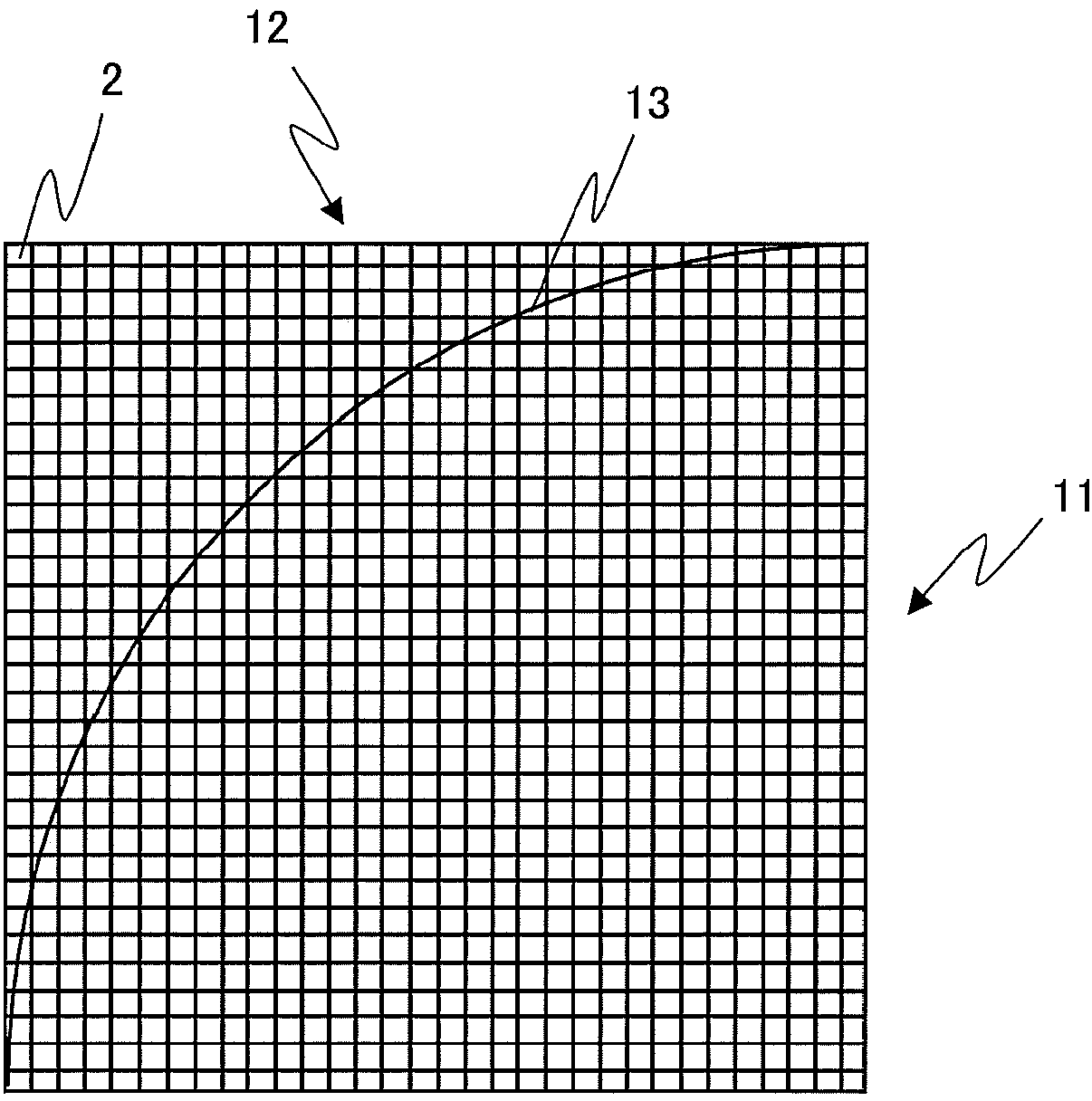
[0036] figure 2 It is an enlarged view of the upper left corner of the display area 11 of the display device 100 . A plurality of pixels 2 are arranged in a matrix in the display device 100 . Each pixel 2 has a rectangular shape. exist figure 2 In , the lower side of the boundary line 13 of the display area is the display area 11 , and the upper side is the non-display area 12 . Rectangular pixels 2 are arranged not only in the display area 11 but also in the non-display area 12 .
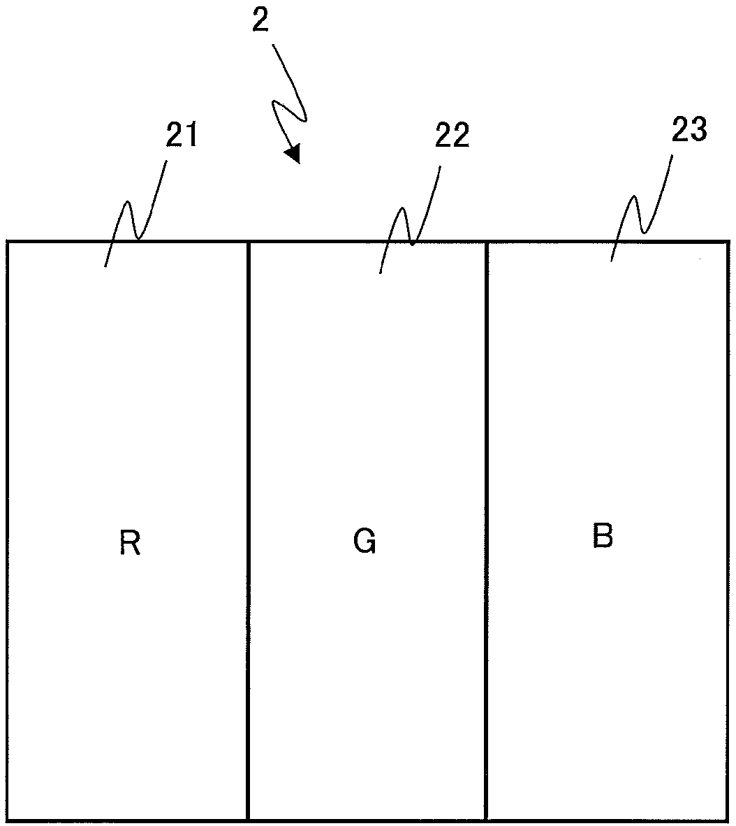
[0037] Such as image 3 As shown, one pixel 2 is composed of three sub-pi...
no. 2 Embodiment approach
[0055] In the first embodiment, the case where the non-display area 12 is black has been described. In the second embodiment, a case where the non-display area 12 is white will be described. In this case, a pixel in which all sub-pixels are located in the non-display area 12 may be covered with a white film, or the pixel may be displayed in white.
[0056] In the case where the non-display area 12 is white, if the luminance of a pixel in which all sub-pixels are located in the non-display area 12 is set as T1, and the luminance of a pixel in which all sub-pixels are located in the display area 11 is set as T2, the boundary pixel The brightness of is set to T3, then the relationship of the following formula (4) is established. Here, the luminance value T2 of a pixel whose all sub-pixels are located in the display area 11 refers to the luminance value of a pixel in which all sub-pixels are located in the display area 11 among pixels adjacent to the target boundary pixel.
[00...
PUM
 Abstract
Description
Claims
Application Information
 - R&D
- Intellectual Property
- Life Sciences
- Materials
- Tech Scout
- Unparalleled Data Quality
- Higher Quality Content
- 60% Fewer Hallucinations
Browse by: Latest US Patents, China's latest patents, Technical Efficacy Thesaurus, Application Domain, Technology Topic, Popular Technical Reports.
© 2025 PatSnap. All rights reserved.Legal|Privacy policy|Modern Slavery Act Transparency Statement|Sitemap|About US| Contact US: help@patsnap.com