Illuminable ultraviolet disinfection wall hanging lamp
An ultraviolet and disinfection tank technology, applied in disinfection, irradiation, sanitary equipment for toilets, etc., can solve the problems of large desktop platform area, occupying desktop platform area, difficult to achieve wall-mounted form, etc., to achieve the effect of simple installation
- Summary
- Abstract
- Description
- Claims
- Application Information
AI Technical Summary
Problems solved by technology
Method used
Image

Examples
Embodiment
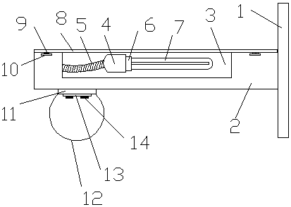
[0020] A UV sterilizing wall lamp that illuminates, such as figure 1 , including a mounting plate 1 and an ultraviolet disinfection assembly, and also includes an installation seat 2 and a lighting assembly, the installation seat 2 is provided with a disinfection tank 3, and the disinfection tank 3 is provided with an ultraviolet disinfection assembly, and the ultraviolet disinfection assembly includes a lamp holder 4, a bellows 5, Threaded lamp cap 6 and ultraviolet lamp tube 7, threaded lamp cap 6 is connected to ultraviolet lamp tube 7, threaded lamp cap 6 is threadedly connected to lamp holder 4, lamp holder 4 is connected to disinfection tank 3 through bellows 5, and one end of mounting seat 2 is connected to On the mounting plate 1 , the lighting assembly is arranged at the other end of the mounting base 2 .
[0021] This kind of ultraviolet disinfection wall-mounted lamp that can be illuminated can realize the function of sterilizing and killing mites by setting the dis...
PUM
 Abstract
Description
Claims
Application Information