Special tooling for jack block processing and assembly structure for jack block processing

A jacking block and tooling technology, applied in metal processing equipment, metal processing machinery parts, manufacturing tools, etc., can solve problems such as inability to repair a single piece, increase repair cost, and long processing time, so as to achieve convenient clamping and improve production efficiency , the effect of reducing production costs

Active Publication Date: 2020-02-18
HASCO VISION TECHNOLOGY CO LTD
View PDF6 Cites 0 Cited by
  • Summary
  • Abstract
  • Description
  • Claims
  • Application Information

AI Technical Summary

Problems solved by technology

[0002] The top block is a common part in the injection mold. Usually, when processing the top block, it is necessary to install the top block to be processed in the insert and process it together with the insert. On the one hand, the processing time is longer, and on the other hand, when it comes to repairing It also needs to be installed in the insert together, and cannot be repaired in a single piece, which is not only time-consuming, but also increases the cost of repair

Method used


Image

  • Special tooling for jack block processing and assembly structure for jack block processing
  • Special tooling for jack block processing and assembly structure for jack block processing
  • Special tooling for jack block processing and assembly structure for jack block processing

Examples


Embodiment Construction

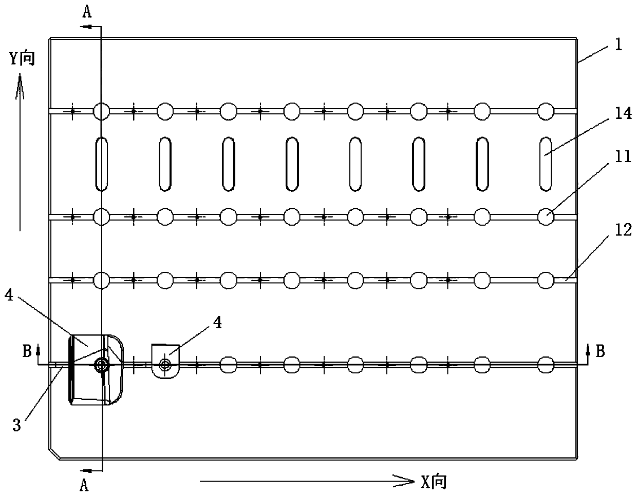
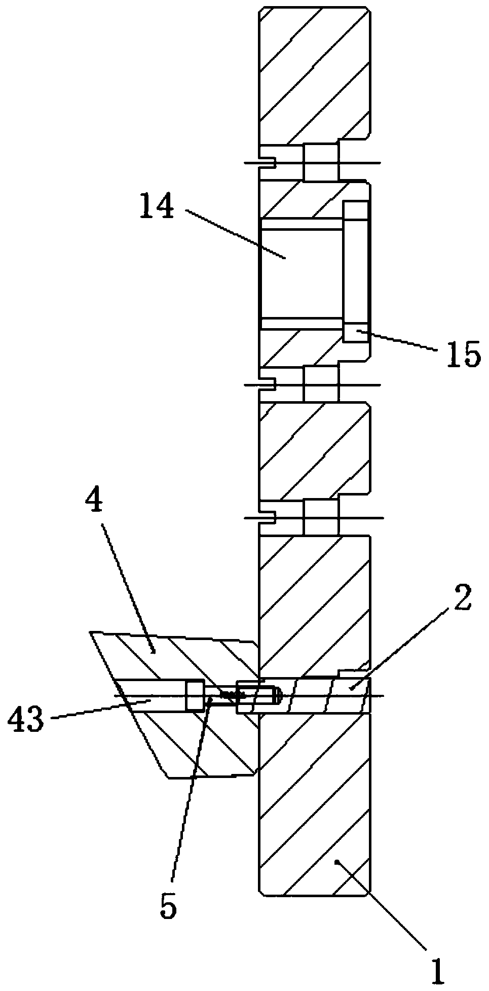
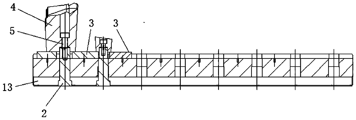
[0028] The invention discloses a special tooling for jack block processing, such as Figure 1-5 As shown, it includes a process plate 1, a cylindrical locating pin 2 and a square locating pin 3. The process plate is provided with a number of cylindrical pin holes 11 that penetrate up and down. The upper and lower planes of the process plate are respectively provided with upper flat bottoms. Groove 12 and lower flat-bottomed groove 13, the cross-section of upper and lower flat-bottomed grooves all is rectangular. The cylindrical pin hole runs through the upper flat-bottomed groove and the lower flat-bottomed groove, the groove width of the lower flat-bottomed groove is greater than the diameter of the cylindrical pin hole, and the groove bottom area of ​​the lower flat-bottomed groove around the cylindrical pin hole is used as The axial positioning surface of the cylindrical positioning pin. The upper end of the cylindrical positioning pin is axially provided with a screw hole...


PUM


Abstract

The invention relates to a special tool for top block machining and top block machining assembling structure. An upper plane and a lower plane of a process board are correspondingly provided with an upper flat bottom groove and a lower flat bottom groove, a cylindrical pin hole penetrates through the upper flat bottom groove and the lower flat bottom groove, and a screw hole is axially formed in the upper end of a cylindrical positioning pin; the lower end of the cylindrical positioning pin is provided with a boss extending outwards, and the cylindrical positioning pin is matched with a cylindrical pin hole in the mounting state; the boss hooks the bottom surface of the lower flat bottom groove, and the upper portion of the cylindrical positioning pin penetrates out of an upper plane of aprocess plate; a square positioning pin is fixed in each of the upper flat bottom grooves in the two sides of the cylindrical positioning pin, the bottom surfaces of the square positioning pins and one side surfaces of the square positioning pins are positioning surfaces, and the upper parts of the square positioning pins are exposed out of the upper plane of the process plate and are not higher than the cylindrical positioning pin; the top block is placed on the process plate, and through grooves span over the square positioning pins and are in clearance fit with the square positioning pins;and the upper portion of the cylindrical positioning pin is coordinated with an ejector rod hole, and the cylindrical positioning pin is fastened with an ejector block screw. The special tool is simple, convenient and small in size, and capable of saving the time of clamping and tool setting, and is suitable for one-step machining of a plurality of top blocks with multiple specifications.

Description

technical field [0001] The invention relates to a special fixture, in particular to a special fixture for processing a top block for an injection mold. Background technique [0002] The top block is a common part in the injection mold. Usually, when processing the top block, it is necessary to install the top block to be processed in the insert and process it together with the insert. On the one hand, the processing time is longer, and on the other hand, when it comes to repairing It also needs to be installed in the insert together, and it cannot be repaired in one piece, which is not only time-consuming, but also increases the cost of repair. Contents of the invention [0003] In order to solve the above problems, the present invention provides a special tool for jack block processing and a jack block processing assembly structure. The tool is simple and compact, saves time for clamping and tool setting, and is suitable for various jack blocks. [0004] Main technical s...

Claims


Application Information

Patent Timeline
Patent Type & Authority Patents(China)
IPC IPC(8): B23Q3/06
CPCB23Q3/061B23Q3/062
Inventor 马婷婷吴明华徐惠倪志
Owner HASCO VISION TECHNOLOGY CO LTD
Why Eureka
Try Eureka