
Manufacturing method of micro-drive robot arm

A robotic arm and micro-drive technology, applied in manipulators, program-controlled manipulators, claw arms, etc., can solve the problems of insufficient detection sensitivity of piezoelectric materials, long post-processing/assembly iterations, etc., to improve stability, eliminate response lag, The effect of simplifying the preparation process

Active Publication Date: 2018-09-04
郭玉华
View PDF8 Cites 0 Cited by
  • Summary
  • Abstract
  • Description
  • Claims
  • Application Information

AI Technical Summary

Problems solved by technology

[0003] The object of the present invention is just to provide a kind of micro-drive robot arm preparation method in order to solve the above problems, to solve the unfavorable factors of multiple preparation processes and assembly procedures, post-processing / assembly and lengthy iterations in the prior art; especially for conventional The piezoelectric sensor, the combination of piezoelectric materials has insufficient detection sensitivity, and the conventional electrode structure cannot provide a stable electrical connection during frequent deformation.

Method used


Image

  • Manufacturing method of micro-drive robot arm
  • Manufacturing method of micro-drive robot arm
  • Manufacturing method of micro-drive robot arm

Examples


Embodiment 1

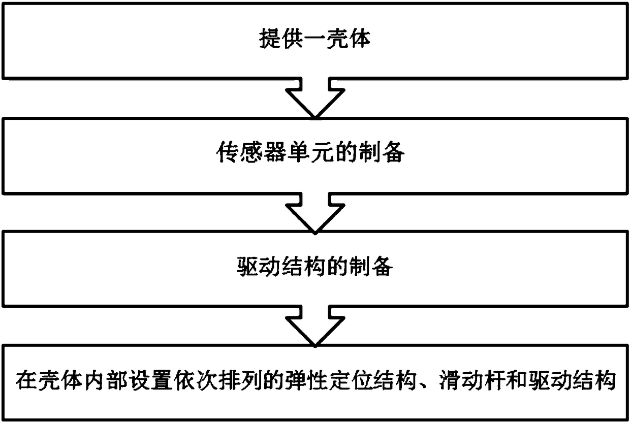
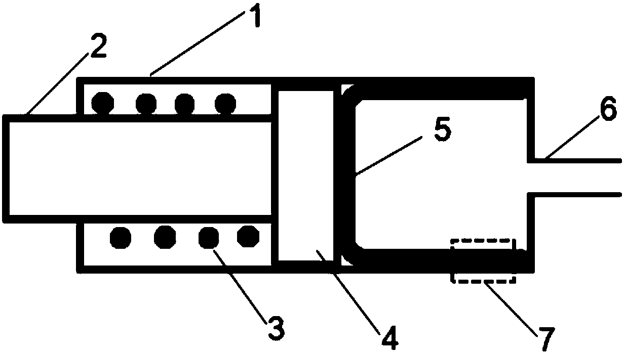
[0023] A flow chart of the preparation of a micro-actuated robot arm is shown in figure 1 shown. Firstly, a casing 1 is provided, and the casing 1 includes through holes at its two ends;

[0024] Inside the housing 1, an elastic positioning structure 3, a sliding rod 2 and a driving structure 5 arranged in sequence are arranged, wherein the elastic positioning structure 3 is used for elastically positioning the sliding rod 2, and the sliding rod 2 is positioned on the The through hole at one end of the housing 1 protrudes, and the driving structure 5 is connected with a driving tube 6, and the driving tube 6 is connected to the driving structure 5 through the through hole at the other end of the housing 1;

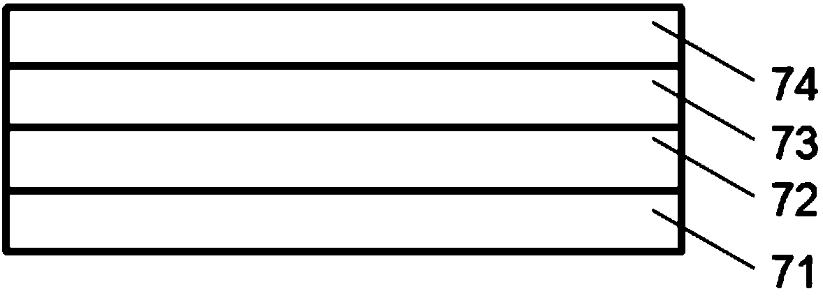
[0025] The driving structure 5 is a cavity structure made of polydimethylsiloxane, and the cavity structure is placed in a mold by placing liquid polydimethylsiloxane in the side wall of the cavity structure. The sensor unit 7 is implanted, and the driving structure 5 is...

Embodiment 2

[0028] Embodiment 2 provides a support arm structure 3, two opposing micro-drive robot arms 11 and 12 are arranged on one side of the support arm structure 3, and the clamping operation of the object can be realized by utilizing the expansion and contraction of the two micro-drive robot arms ,Such as Figure 5 As shown, wherein the micro-driven robot arms 11 and 12 are prepared by the method described in Example 1.


PUM


Abstract

The invention discloses a manufacturing method of a micro-drive robot arm. According to the method, a sensor is implanted into a driving structure, so that integrated manufacturing of the sensor and the driving structure is realized, the manufacturing process is simplified, and the response delay is eliminated; and meanwhile, a composite piezoelectric material composite layer is used, so that thesensor with relatively high deformation detection sensitivity is formed.

Description

technical field [0001] The invention relates to the field of micro-drive devices, in particular to a method for preparing a micro-drive robot arm. Background technique [0002] Micro-driven robots have been applied to various aspects of industry, life and scientific research. They consist of a series of subsystems, such as sensors, actuators and controllers, which together form a robot capable of precise control. Numerous designs focus on the key components of the robot structure and actuators, in order to further improve the accuracy and stability of the operation. Drives can be divided into the following four categories, thermal drive, electric drive, optical drive and magnetic drive. Most of the existing micro-actuators adopt a separate structure of the driving device and the sensing device, which leads to the hysteresis of the detection and is not conducive to the response speed of the actuator; at the same time, for the discrete structure, multiple preparation process...

Claims


Application Information

Patent Timeline
Patent Type & Authority Applications(China)
IPC IPC(8): B25J18/00B25J9/14B25J13/08
CPCB25J9/142B25J13/087B25J18/00
Inventor 郭玉华
Owner 郭玉华
Learn More