Eureka AIR delivers breakthrough ideas for toughest innovation challenges, trusted by R&D personnel around the world.

Self-lubricating dust-proof bearing

A dust-proof bearing and self-lubricating technology, which is applied to bearing components, shafts and bearings, mechanical equipment, etc., can solve the problems of equipment loss, large friction between dust cover and inner ring, waste of lubricating oil, etc., to prolong the service life, Prevents excessive spillage and excellent lubricating effect

Inactive Publication Date: 2018-09-04
杨胜
View PDF5 Cites 4 Cited by
  • Summary
  • Abstract
  • Description
  • Claims
  • Application Information

AI Technical Summary

Problems solved by technology

[0005] In the above patent document 1, the centrifugal block is used to squeeze the oil storage sponge to realize the addition of lubricating oil to the bearing. However, as the rotation speed increases, the lubricating oil on the oil storage sponge is quickly dried up by the agent, resulting in a waste of lubricating oil. If the rotation speed is not enough, the lubricating oil on the oil storage sponge cannot be squeezed out, and the lubrication effect cannot be achieved.
[0006] In Patent Document 2, although dustproof measures have been taken for the bearing, only a dustproof cover is added, but the friction between the dustproof cover and the inner ring is large, causing serious wear and tear on the equipment

Method used


Image

  • Self-lubricating dust-proof bearing
  • Self-lubricating dust-proof bearing
  • Self-lubricating dust-proof bearing

Examples


Embodiment Construction

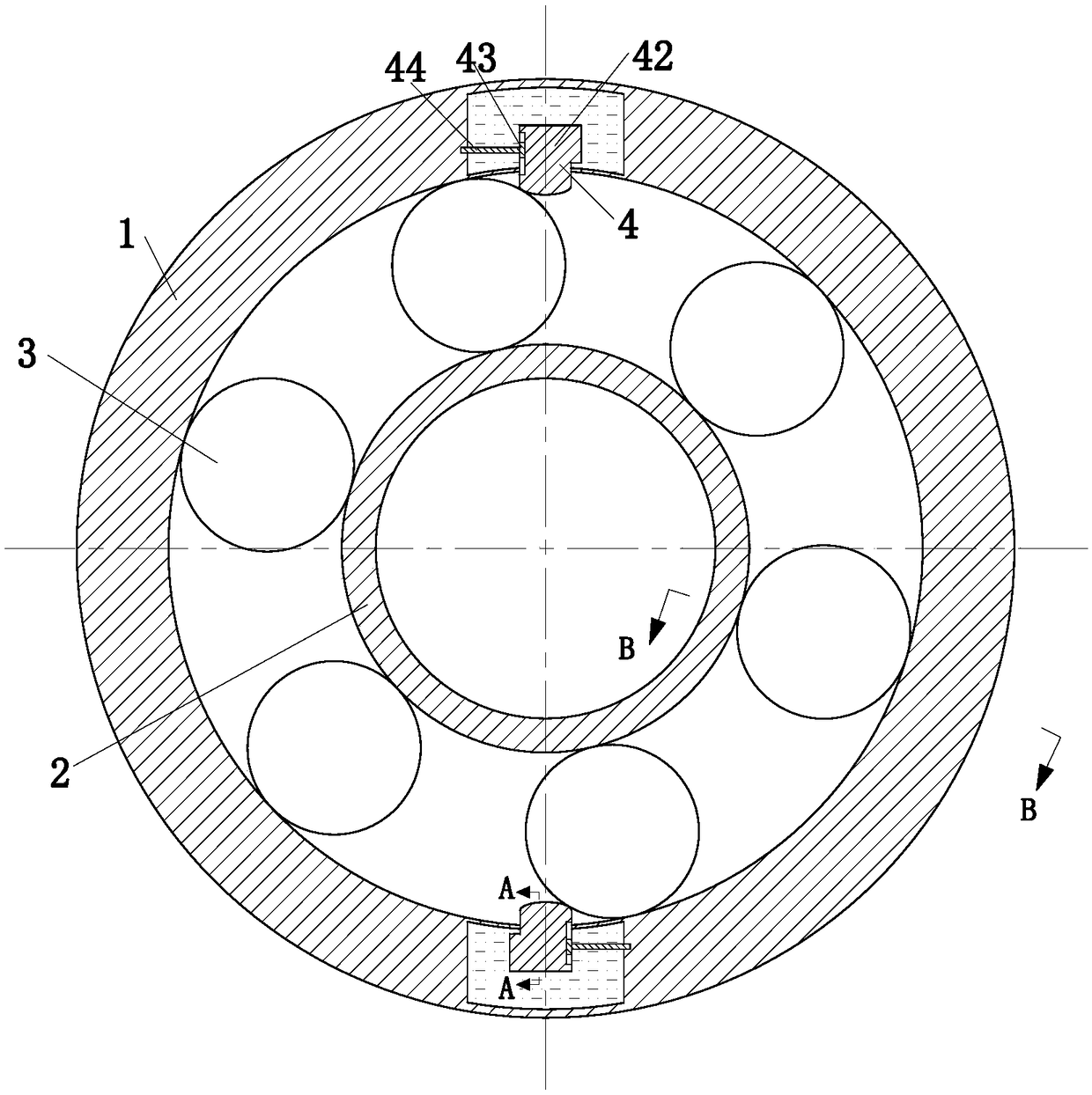
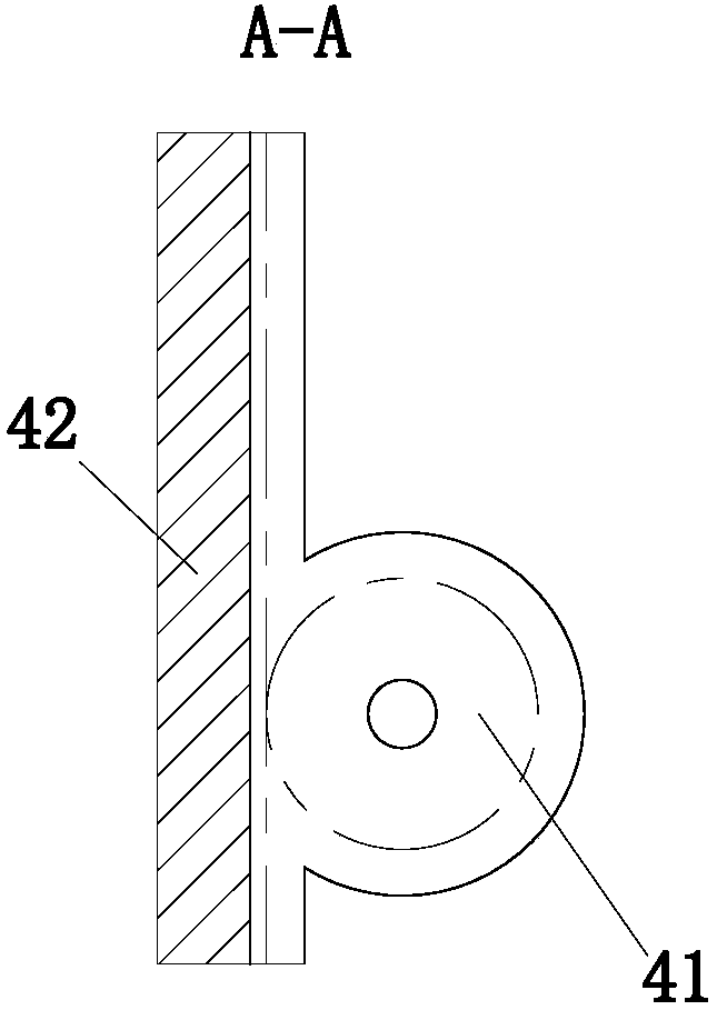
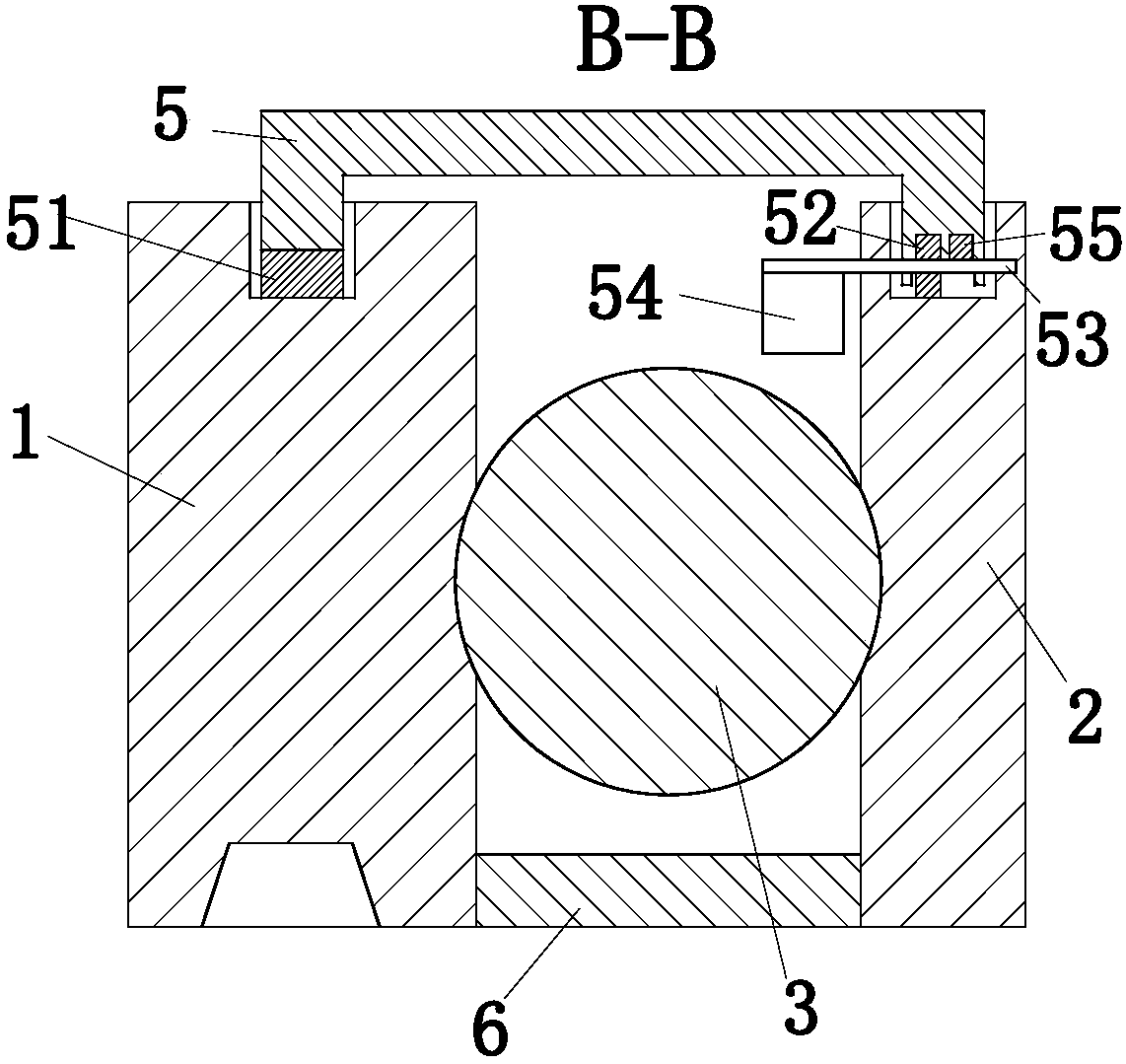
[0023] use Figure 1-Figure 5 The structure of the self-lubricating dust-proof bearing according to one embodiment of the present invention will be described below.

[0024] Such as figure 1 As shown, the assembly method of the bearing assembly described in the present invention includes an outer ring 1, an inner ring 2, a ball 3, a lubrication module 4, a dust cover 5 and a dust pad 6, and the outer ring 1 and the inner ring Balls 3 are arranged between the 2, the outer ring 1 is provided with a side wall hollow chamber and a groove 1, the groove 1 communicates with the hollow chamber, and the top of the outer ring 1 is provided with a groove 2; The lubricating module 4 is located in the hollow chamber, and the lubricating module 4 is used to add lubricating oil to the balls 3; the top of the inner ring 2 has a groove three; the dust cover 5 is installed on the groove two and the inner groove 3 of the ring 2; the dust-proof pad 6 is installed on the bottom of the outer ring...


PUM


Abstract

The invention belongs to the technical field of bearings, and particularly relates to a self-lubricating dust-proof bearing. The self-lubricating dust-proof bearing comprises an outer ring, an inner ring, rolling balls, lubricating modules, a dust-proof cover and a dust-proof pad. The rolling balls are arranged between the outer ring and the inner ring, cavities and a first groove are formed in the side wall of the outer ring, the first groove communicates with the cavities, a second groove is formed in the top of the outer ring, the lubricating modules are located in the cavities and used foradding lubricating oil to the rolling balls, a third groove is formed in the top of the inner ring, the dust-proof cover is installed in the second groove of the outer ring and the third groove of the inner ring, and the dust-proof pad is installed at the bottom of the outer ring and located between the outer ring and the inner ring. Through mutual cooperation of the lubricating modules, the rolling balls and the dust-proof cover, the lubricating oil is added to the rolling balls by using the rolling balls to extrude the lubricating modules constantly, and lubrication is provided for the rolling balls. The dust-proof cover not only can cut off dust, but also can prevent excessive lubricating oil from overflowing.

Description

technical field [0001] The invention belongs to the technical field of bearings, in particular to a self-lubricating dust-proof bearing. Background technique [0002] At present, the bearings used on the rotating shaft are generally used, because after the bearings have been used for a long time, the bearings need to be maintained and lubricated, so there are some conveniently lubricated bearings, but these effects have destroyed the structure of the bearings, and it is easy for the entire bearing to work. Noise is generated during the process, and because some self-lubricating bearings cannot be manually controlled during the lubrication process, too much lubricating oil is often added, or the lubricating oil that has not been used by the bearing is used for one time When put into use, there is often too much lubricating oil on the bearing, so that the whole bearing will throw the lubricating oil out of the bearing when it is working or seep from the bearing when it stops w...

Claims


Application Information

Patent Timeline
Patent Type & Authority Applications(China)
IPC IPC(8): F16C33/66F16C33/78F16C33/82
CPCF16C33/6659F16C33/7806F16C33/784F16C33/82
Inventor 杨胜
Owner 杨胜
Why Eureka
Eureka Blog
Learn More