Pipeline fast cutoff device

A shut-off device and fast technology, applied in valve devices, valve operation/release devices, pipe components, etc., can solve problems such as pipe bursting, loose pipe joints, waste of raw materials, etc., and achieve the effect of convenient emergency use and waste prevention.

Inactive Publication Date: 2018-09-04
叶聪梅
View PDF5 Cites 0 Cited by
  • Summary
  • Abstract
  • Description
  • Claims
  • Application Information

AI Technical Summary

Problems solved by technology

[0002] It is known that in industrial equipment, pipelines are the main carrier for transporting liquids. The existing control method is to install valves on pipelines to control flow and stop flow. Due to pipeline quality, pipeline aging or excessive pressure, etc., often In the event of loose pipe joints or pipe bursts, maintenance personnel cannot approach and close the valve due to the extremely high pressure of the liquid being transported, resulting in a large waste of raw materials

Method used


Image

  • Pipeline fast cutoff device
  • Pipeline fast cutoff device
  • Pipeline fast cutoff device

Examples


Embodiment Construction

[0025] The present invention can be explained in more detail through the following embodiments. The purpose of disclosing the present invention is to protect all changes and improvements within the scope of the present invention. The present invention is not limited to the following embodiments;

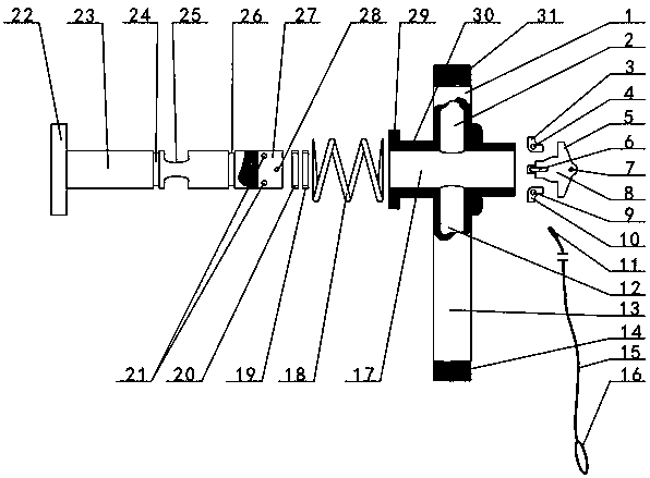
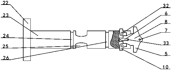
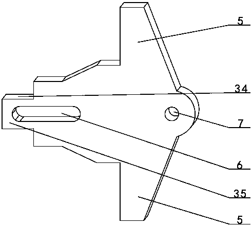
[0026] Attached Figure 1~5 The described pipeline quick cut-off device includes a cross-shaped tube, a movable valve stem 23, a rubber sealing ring A19, a rubber sealing ring B20, a spring 18, a corner plate A 3, a corner plate B 10, and a pull plate 8. An expanding ring 22 is provided at one end of the movable valve stem 23, and an annular groove A24 and an annular groove B26 are respectively provided on both sides of the middle part close to the movable valve stem 23. The valve stem 23 is moved between the annular groove A24 and the annular groove B26. A liquid passage hole 25 is provided near the annular groove A24; the outer end of the connecting pipe A1 of the cross-shaped pipe is...


PUM


Abstract

The invention relates to a pipeline cutoff device, in particular to a pipeline fast cutoff device. A connecting pipe B (13) and a connecting pipe A (1) are connected with the middle of a valve pipe (30). A penetrating hole (25) of a moving valve rod (23) penetrating in a valve pipe through hole (17) corresponds to a pipe hole A (2) or blocks the pipe hole A and a pipe hole B (12). The two ends ofa spring (18) arranged on the moving valve rod in a sleeving manner abut against the opposite faces of one end of the valve pipe and an expanding ring (22) correspondingly. A hole A (4) of an angle plate A (3) and a hole C (9) of an angle plate B (10) are connected to the two sides of the groove bottom of a clamp groove (27) through pin shafts (32) correspondingly. The opposite faces of a horizontal plate of the angle plate A and a horizontal plate of the angle plate B abut against an extending plate (35) at the inner end of a pull plate (8). A long round groove (6) of the middle part of the pull plate is connected to a middle groove opening of the clamp groove through a sliding rod (33). According to the pipeline fast cutoff device, when a pipeline connector loosens or a pipeline bursts,the pipeline can be fast closed off by pulling the pull plate.

Description

Technical field [0001] The invention relates to a pipeline flow cut-off device, in particular to a pipeline fast cut-off device. Background technique [0002] It is known that in industrial equipment, pipelines are the main carrier for liquid transportation. The existing control method is to install valves on the pipelines to control flow and cut off. Due to pipeline quality, pipeline aging or excessive pressure, etc., often Loose pipe joints or pipe bursts occur. Due to the extremely high pressure of many liquids, maintenance personnel cannot close the valves, resulting in a lot of waste of raw materials. Summary of the invention [0003] In order to overcome the shortcomings in the background art, the present invention discloses a rapid pipeline shutoff device. When the pipeline interface is loose or the pipeline bursts, the pull plate can be driven by the force of the spring to drive the moving valve stem to quickly close the pipeline, which effectively prevents Waste of raw m...

Claims


Application Information

Patent Timeline
IPC IPC(8): F16L55/16F16K1/32F16K1/36F16K31/60
CPCF16L55/1612F16K1/32F16K1/36F16K31/602
Inventor 叶聪梅
Owner 叶聪梅
Why Eureka
Try Eureka