Light heating roof

A single, glass tile technology, applied in the field of building heating, can solve the problems of poor heating effect and volume limitation, and achieve the effect of low cost and integration

Inactive Publication Date: 2018-09-04
徐立霜
View PDF0 Cites 1 Cited by
  • Summary
  • Abstract
  • Description
  • Claims
  • Application Information

AI Technical Summary

Problems solved by technology

Various existing solar heating equipment are fixed on the roof, use the collected solar energy to heat the air, and then pass it into the room, the volume is limited, and the heating effect is not good

Method used


Image

  • Light heating roof
  • Light heating roof
  • Light heating roof

Examples


Embodiment Construction

[0023] The following will clearly and completely describe the technical solutions in the embodiments of the present invention with reference to the drawings in the embodiments of the present invention.

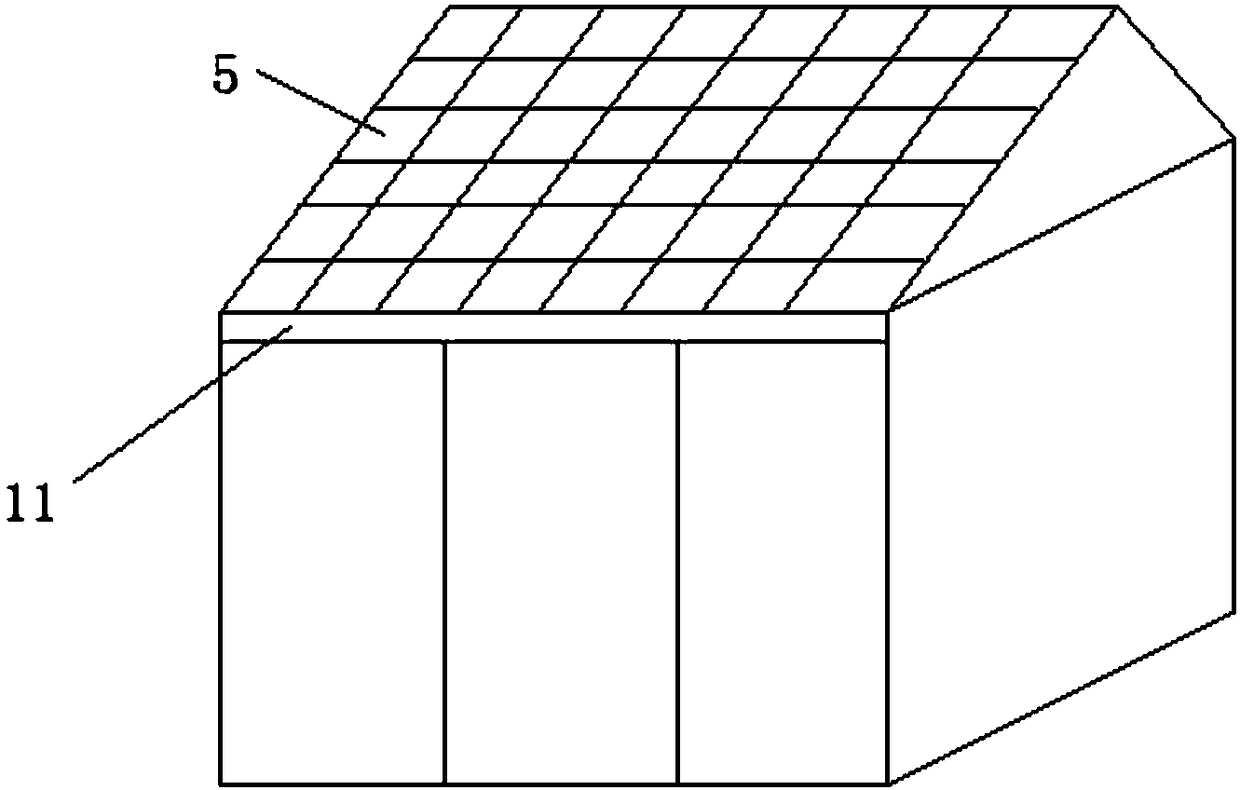
[0024] The invention provides a light and warm roof, such as figure 1 As shown, the light-heating roof makes full use of the roof structure of the current building to meet the needs of large-area heating, has high heating efficiency, and realizes the integration of air-heating buildings.

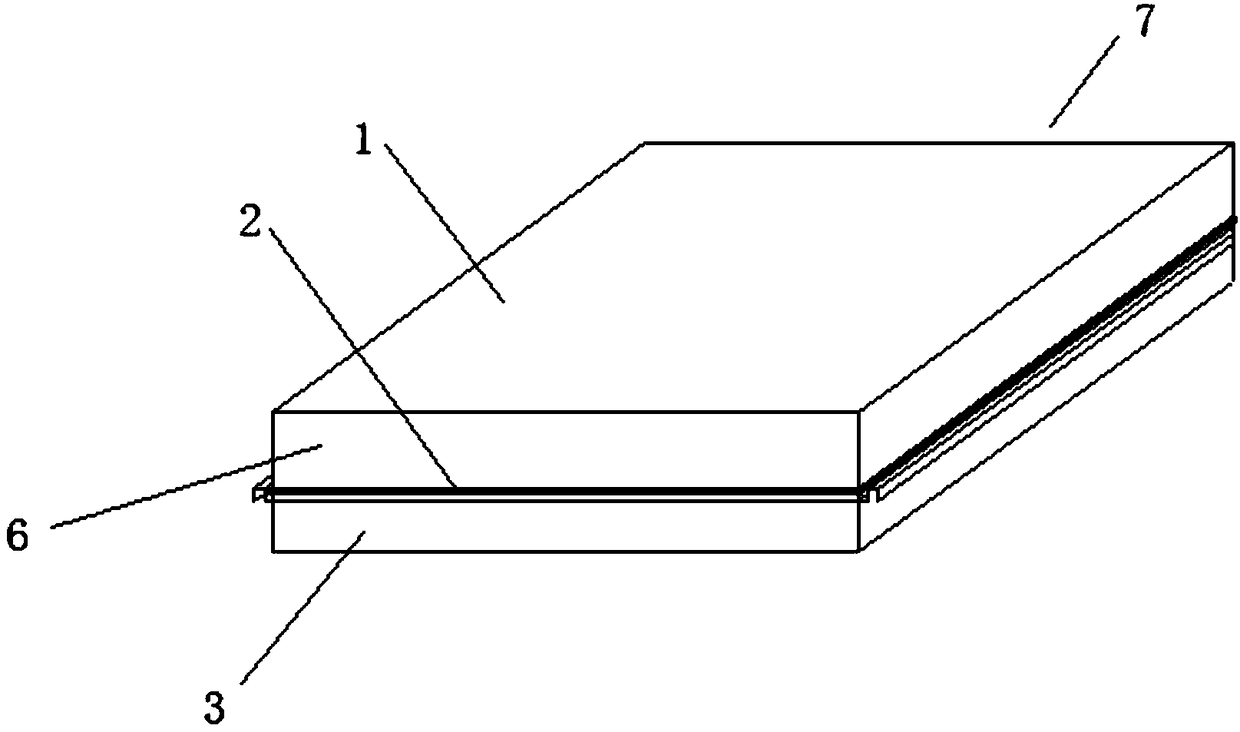
[0025] Such as figure 1 As shown in the light and warm roof, the sunny side of the roof includes several light and warm glass tiles 5 connected together, such as image 3 and Figure 4 As shown, the light-warming glass tile 5 includes a glass tile 1 on the outermost layer, a heat-collecting layer in the middle, and an insulating layer 3 at the bottom. There is an air circulation channel between the glass tile 1 and the heat-collecting layer, and the heat-collecting layer includes The supp...


PUM


Abstract

The invention discloses a light heating roof. The sunny surface of the roof comprises a plurality of light heating glass tiles connected together; each of the light heating glass tiles comprises the outermost glass tile, the middle heat collecting layer and a bottom insulating layer; an air circulating channel is formed between the glass tile and the heat collecting layer; the heat collecting layer comprises a supporting plate and a heat collecting membrane plated to the surface of the supporting plate; the heat collecting membrane is located on the side, facing the glass tile, of the supporting plate and the insulating layer is located on the other side; a fan is arranged transversely at the air outlet of the top of the roof, and is connected to warm air outlets of rooms through pipelines; an air duct switching device is arranged in the air inlet of the bottom of the roof and the air duct switching device can communicate the air inlet outdoors or indoors. The light heating roof heatsoutdoor air by means of the whole heating area of the roof to provide hot air indoors and carry out indoor air circulation, so that the light heating roof is high in heating efficiency and low in cost, and existing insulating layers and tiles of the roof are replaced, so that light heating and building are integrated.

Description

technical field [0001] The invention relates to the technical field of building heating, in particular to a light-heating roof. Background technique [0002] With the improvement of people's living standards, people put forward higher and higher requirements for the comfort of the indoor environment, which brings more and more heating demands for various buildings in cities and towns. Most of the traditional building heating uses municipal central heating and air-conditioning heating, which is costly, wastes resources, and increases air pollution. [0003] Thus, people have researched and developed various equipment utilizing solar energy for heating, adopting heat collectors to collect solar energy, and providing warm air to the room is a more popular heating method recently. This method is environmentally friendly and energy-saving, and is deeply loved by people. Various existing solar heating devices are fixed on the roof, use the collected solar energy to heat the air,...

Claims


Application Information

Patent Timeline
Patent Type & Authority Applications(China)
IPC IPC(8): F24S20/69F24D15/02
CPCF24D15/02Y02B10/20
Inventor 徐立霜
Owner 徐立霜
Why Eureka
Try Eureka