Automobile heat pump system and control method

A technology for heat pump systems and automobiles, applied in electric vehicles, battery temperature control, battery/fuel cell control devices, etc., can solve the problem of low utilization rate of waste heat

Pending Publication Date: 2020-10-23
的卢技术有限公司
View PDF0 Cites 9 Cited by
  • Summary
  • Abstract
  • Description
  • Claims
  • Application Information

AI Technical Summary

Problems solved by technology

However, the waste heat utilization rate of this method is low, and part of the waste heat still needs to be dissipated into the air.

Method used


Image

  • Automobile heat pump system and control method
  • Automobile heat pump system and control method
  • Automobile heat pump system and control method

Examples


Embodiment Construction

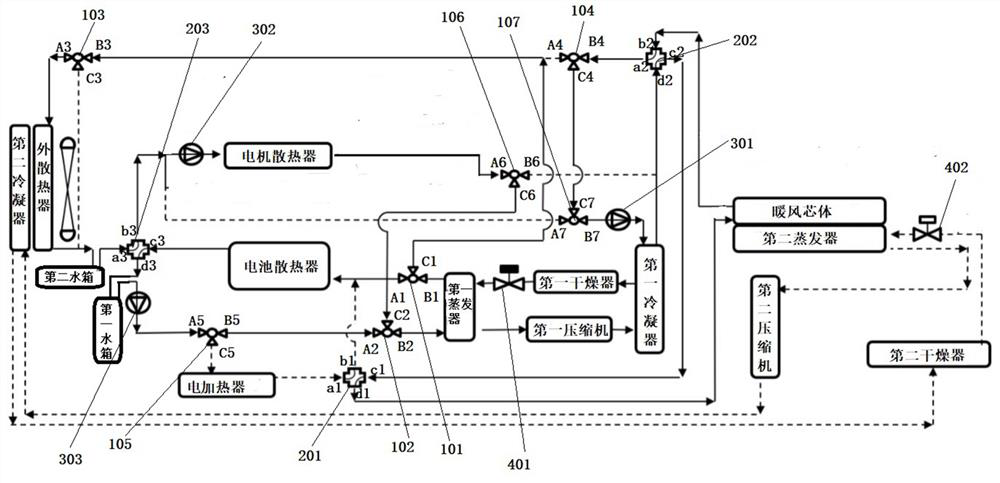
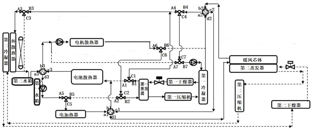
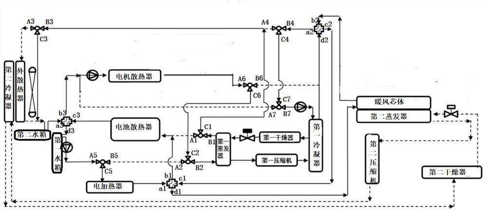
[0057] Such as Figure 1 to Figure 4 , The present invention proposes an automobile heat pump system, which includes a vehicle equipment refrigeration unit and a passenger compartment heating unit. Figure 1 to Figure 4 The solid line is the flow pipeline, and the dashed line is the closed pipeline.

[0058] The vehicle equipment refrigeration unit includes a first compressor, a first condenser, a first evaporator and a vehicle equipment radiator group.

[0059] The passenger compartment heating unit includes a heater core.

[0060] When the passenger compartment heating unit obtains heat from the waste heat of vehicle equipment, the refrigerant compressed by the first compressor enters the hot end of the first condenser, and the heat medium of the warm air core enters the first condenser Cold end: the heat medium of the warm air core flows back to the warm air core after exchanging heat with the refrigerant in the first condenser to heat up; the air from the cold end of the...


PUM


Abstract

The invention discloses an automobile heat pump system and a control method. The automobile heat pump system comprises a warm air core body and an automobile equipment refrigeration unit. The automobile equipment refrigeration unit comprises a first compressor, a first condenser, a first evaporator and an automobile equipment radiator set. A heat medium of the warm air core body exchanges heat with a refrigerant in the first condenser to be heated and then flows back to the warm air core body; cold end air of the warm air core body is used for heating air of a passenger compartment; a refrigerant exchanges heat and is cooled in the first condenser and then flows into the cold end of the first evaporator; a cold medium of the automobile equipment radiator set enters the hot end of the firstevaporator, exchanges heat with a refrigerant for cooling and then flows back to the automobile equipment radiator set to be used for heat dissipation of automobile equipment. A refrigerant exchangesheat in the first evaporator, is heated and then flows into an inlet of the first compressor. Motor waste heat, battery waste heat and external air heat are utilized to the maximum extent, and an automobile air conditioner does not need to switch heating through a refrigerant loop; the development cost and the automobile heating power consumption are reduced.

Description

technical field [0001] The invention belongs to the field of heat pumps, in particular to an automobile heat pump system and a control method. Background technique [0002] The current heat pump system of new energy vehicles is mainly based on the switching of the refrigerant circuit of the automobile air conditioner to realize the heat pump system. When the passenger compartment needs cooling, the evaporator absorbs the heat inside the car and dissipates it outside the car through the condenser. When the passenger compartment needs heating, the outdoor condenser acts as an evaporator to absorb the heat outside the vehicle, and the evaporator acts as a condenser to release heat to the passenger compartment. This heating method of switching refrigerant circuits for air conditioners has high energy consumption, complicated control, and high difficulty in development. [0003] In the prior art, in order to save energy, the waste heat of the motor and the battery equipment is ...

Claims


Application Information

Patent Timeline
Patent Type & Authority Applications(China)
IPC IPC(8): B60H1/00B60H1/06B60K1/00B60L58/26B60K11/04H01M10/613H01M10/615H01M10/625H01M10/66
CPCB60H1/00278B60H1/00385B60H1/06B60K1/00B60K11/04B60K2001/005B60K2001/006B60L58/26H01M10/613H01M10/615H01M10/625H01M10/66Y02E60/10Y02T10/70
Inventor 董红军黄轶
Owner 的卢技术有限公司
Why Eureka
Try Eureka