
Automatic thermocouple battery thermal management system

An automatic management and thermocouple technology, applied in secondary batteries, circuits, electrical components, etc., can solve the problems of complex calculation mode, limit heat absorption of insulation jackets, and inability to achieve heat exchange, achieving low cost and broad application prospects. , the effect of fast response

Inactive Publication Date: 2016-11-09
DONGGUAN LILONG BATTERY TECH CO LTD
View PDF3 Cites 0 Cited by
  • Summary
  • Abstract
  • Description
  • Claims
  • Application Information

AI Technical Summary

Problems solved by technology

[0003] The above two battery cooling schemes in the prior art belong to the use of phase change latent heat technology to cool the battery. This technology can realize the cooling of the battery cell. However, if the battery cell works for too long, the insulation cover will absorb heat Since each battery cell is stacked together, heat exchange with the surrounding environment cannot be realized, so this solution is only suitable for the environment where the battery pack is in a short-term working environment
[0004] For the intelligent independent cooling of the battery cells of the battery pack, thermal management is currently carried out through the power management system, but the thermal management of the power supply of the battery pack is too high for the technical requirements of the enterprise, its calculation mode is complicated, and the management effect is not ideal, so it cannot be realized Accurate management of single (cell) batteries, there is no feasible technology at present, and this problem needs to be solved urgently

Method used


Image

  • Automatic thermocouple battery thermal management system

Examples


Embodiment Construction

[0017] The present invention will be further described below in conjunction with the accompanying drawings and embodiments, but the content of the present invention is not limited to the stated scope.

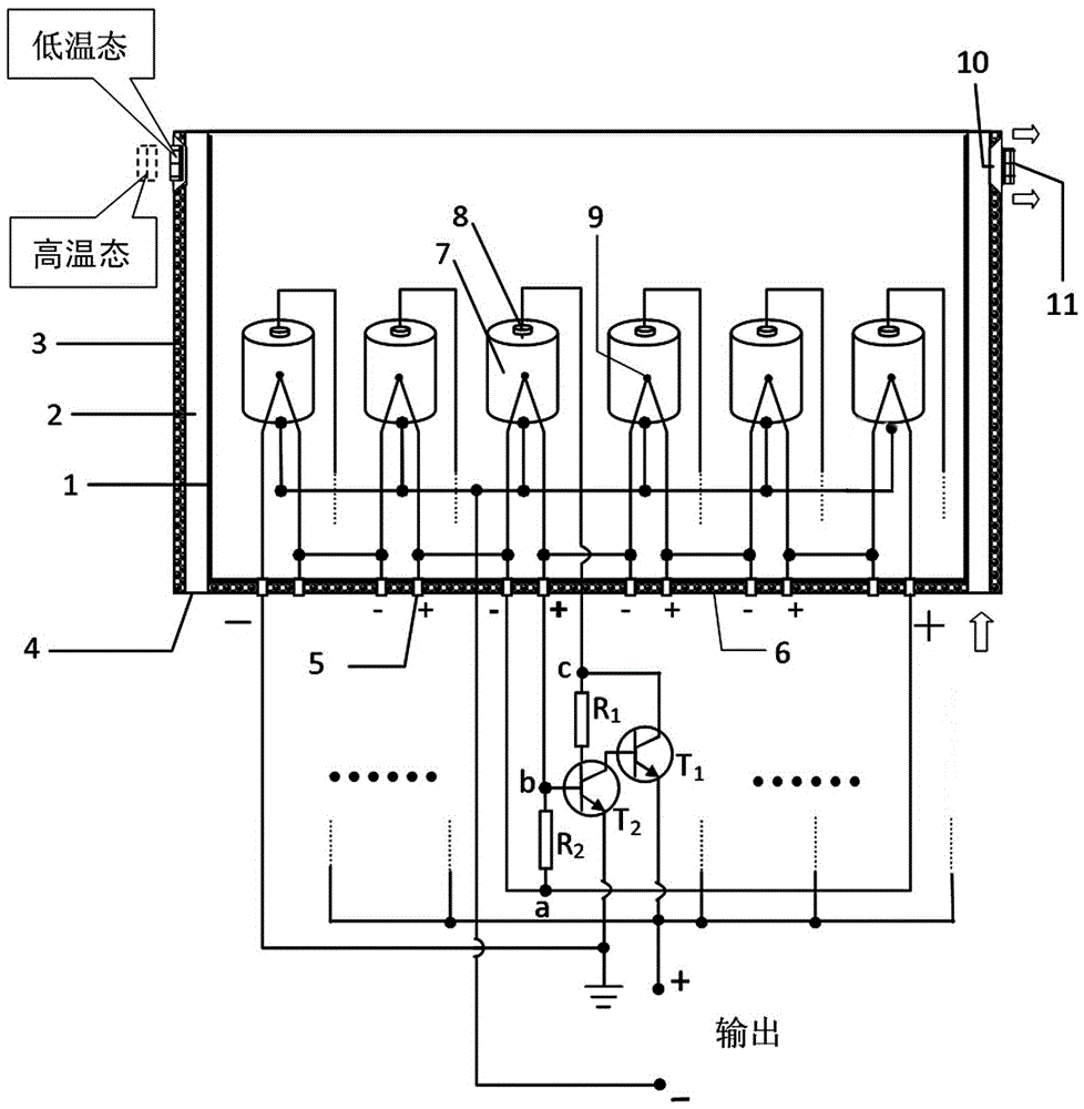
[0018] In the present invention, the inner wall 1 of the battery box and the outer shell 3 form a battery box combination with interlayers on the sides. A series of single cells 7 are arranged in the space on the inner wall of the box. Ventilation window 10, bimetal temperature regulating sheet 11 is contained in the ventilation window 10 place and matches with it. The air convection layer 2 of the interlayer of the battery box body is closed at the top, and an interlayer opening hole 4 is provided at the lower end. The cross section of the ventilation window 10 is a trapezoidal structure with a small inside and a large outside. The bottom layer 6 of the battery box is embedded with the thermocouple voltage output terminal 5, which is welded with two identical thermocouple com...


PUM


Abstract

The invention relates to an automatic thermocouple battery thermal management system, and belongs to the technical field of battery management. The outer walls of all battery cells in a battery pack box make contact with thermocouple measuring terminals, all the thermocouple measuring terminals are connected with corresponding thermocouple voltage output terminals through thermocouple compensating wires, the thermocouple voltage output terminals of all the battery cells are mutually connected in series to form a total thermocouple power supply, a negative pole of the total thermocouple power supply is grounded, the thermocouple voltage output terminals of the battery cells and positive electrodes of the battery cells all have access to corresponding triode amplifying circuits, output terminals of the amplifying circuits are power output of a battery pack, and a positive electrode of the total thermocouple power supply is connected with negative poles of the thermocouple voltage output terminals of all the battery cells. The automatic thermocouple battery thermal management system is simple in circuit, high in reaction speed, low in manufacturing cost, capable of conducting independent current regulation on the battery cells for the storage battery pack formed by intensively stacking the battery cells, intelligent independent cooling is achieved, and the requirement of the battery pack on long-time working can be met.

Description

technical field [0001] The invention relates to a thermocouple battery thermal automatic management system, which belongs to the technical field of battery management. Background technique [0002] At present, in the battery management system, the latest technologies currently mainly include ① lithium battery phase change latent heat insulation cover for cooling. This insulation cover is a low-cost and efficient passive battery heat management technology. The battery serves the purpose of thermal stability and balance protection. The lithium battery cooling jacket used is made of a mixture of 42° phase change material and superconducting thermal material. The heat generated by the lithium battery is absorbed by the phase change material and then the heat is quickly exchanged with the ambient temperature through the superconducting thermal material. The phase change material tends to be at a constant temperature, and the lithium battery is always in a constant temperature en...

Claims


Application Information

Patent Timeline
Patent Type & Authority Applications(China)
IPC IPC(8): H01M10/613H01M10/637H01M10/6561
CPCH01M10/613H01M10/637H01M10/6561Y02E60/10
Inventor 陈峥申江卫肖仁鑫陈蜀乔韩永斌章春元冷小威
Owner DONGGUAN LILONG BATTERY TECH CO LTD
Learn More