A temperature and humidity working condition adjustment system

A technology for regulating systems and working conditions, applied in the field of temperature and humidity working condition regulating systems, can solve problems such as high energy consumption in operation, energy waste, etc., and achieve the effect of reducing energy consumption in operation, reducing useless cooling capacity and dehumidification capacity

Inactive Publication Date: 2015-08-19
广州兰石技术开发有限公司
View PDF5 Cites 0 Cited by
  • Summary
  • Abstract
  • Description
  • Claims
  • Application Information

AI Technical Summary

Problems solved by technology

As a result, the operation energy consumption of conventional laboratories is huge, resulting in a lot of waste of energy

Method used


Image

  • A temperature and humidity working condition adjustment system
  • A temperature and humidity working condition adjustment system

Examples


Embodiment Construction

[0015] The best embodiment of the present invention will be described in detail below with reference to the accompanying drawings.

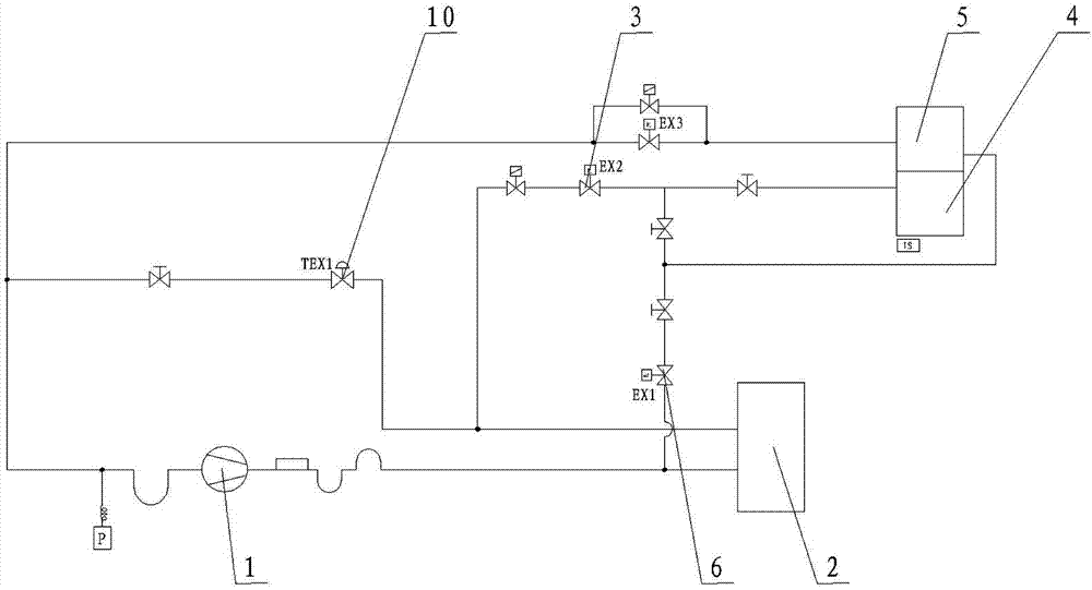
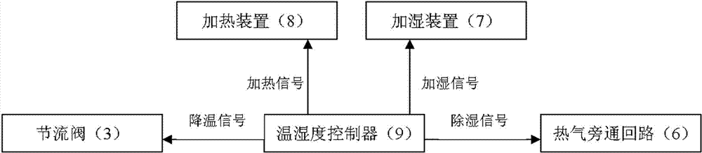
[0016] Such as figure 1 , figure 2 As shown, the temperature and humidity condition adjustment system of the present invention includes a compressor 1, a condenser 2, and a throttle valve 3. The temperature and humidity condition adjustment system also includes a dehumidification coil 4, a sensible heat coil 5, and a hot gas bypass Circuit 6, humidification device 7, heating device 8 and temperature and humidity controller 9, said dehumidification coil 4, sensible heat coil 5, compressor 1, condenser 2 and throttle valve 3 are connected end to end in sequence to form the main circuit , The hot gas bypass circuit 6 is connected between the outlet of the compressor 1 and the inlet of the sensible heat coil 5. The throttle valve 3, the hot gas bypass circuit 6, the humidification device 7 and the heating device 8 are respectively connected to the temp...


PUM


Abstract

The invention discloses a temperature and humidity working condition adjusting system, which comprises a compressor, a condenser, a throttling valve, a dehumidifying coil, a sensible heat coil, a hot air bypass loop, a humidifying device, a heating device and a temperature and humidity controller, wherein the dehumidifying coil, the sensible heat coil, the compressor, the condenser and the throttling valve are connected end to end in sequence through a conduit to form a main loop; the hot air bypass loop is connected between an outlet of the compressor and an inlet of the sensible heat coil; and the throttling valve, the hot air bypass loop, the humidifying device and the heating device are connected with the temperature and humidity controller respectively. According to the temperature and humidity working condition adjusting system, the adjustability of four working conditions is realized through dehumidification of the hot air bypass loop, cooling adjustment of the throttling valve and the conventional heating and humidifying treatment, the useless cold and dehumidification capacity of the working condition adjusting unit are reduced to the greatest extent, and the aim of reducing operation energy consumption is fulfilled, so that the annual operation energy consumption of a constant temperature and constant humidity laboratory during use of the system can be saved by over 30 percent.

Description

Technical field [0001] The invention relates to a temperature and humidity condition adjustment system, belonging to the technical field of temperature and humidity condition adjustment. Background technique [0002] At present, most laboratories with constant temperature and humidity adopt fixed-step cooling and stepless heating and humidification to achieve working condition adjustment. In this refrigeration system, the refrigeration capacity of the refrigerator is not adjustable, and the sensible heat ratio cannot be adjusted, which brings ineffective refrigeration and dehumidification in the process of working condition adjustment. This part of the cooling capacity needs to be balanced by electric heating and electric humidification to achieve The working conditions are stable. As a result, the operation energy consumption of the conventional laboratory is huge, causing a lot of energy waste. Summary of the invention [0003] In order to overcome the shortcomings of the prio...

Claims


Application Information

Patent Timeline
Patent Type & Authority Patents(China)
IPC IPC(8): F24F11/02
Inventor 唐峥罗祥坤
Owner 广州兰石技术开发有限公司
Why Eureka
Try Eureka